Caution, Warning, Step 7 — install electrical connections – Carrier 50JZ-A User Manual
Page 10
10
Step 7 — Install Electrical Connections
UNIT COMPONENT DAMAGE HAZARD
Failure to follow this caution may result in damage to the unit
being installed.
1. Make all electrical connections in accordance with NEC
NFPA 70 (latest edition) and local electrical codes
governing such wiring. In Canada, all electrical
connections must be in accordance with CSA standard
C22.1 Canadian Electrical Code Part 1 and applicable
local codes. Refer to unit wiring diagram.
2. Use only copper conductor for connections between
field--supplied electrical disconnect switch and unit. DO
NOT USE ALUMINUM WIRE.
3. Be sure that high--voltage power to unit is within
operating voltage range indicated on unit rating plate. On
3--phase units, ensure phases are balanced within 2
percent. Consult local power company for correction of
improper voltage and/or phase imbalance.
4. Do not damage internal components when drilling
through any panel to mount electrical hardware, conduit,
etc.
!
CAUTION
ELECTRICAL SHOCK HAZARD
Failure to follow this warning could result in personal injury
or death.
The unit cabinet must have an uninterrupted, unbroken
electrical ground. This ground may consist of an electrical
wire connected to the unit ground screw in the control
compartment, or conduit approved for electrical ground when
installed in accordance with NEC,NFPA 70 National Fire
Protection Association (latest edition) (in Canada, Canadian
Electrical Code CSA C22.1) and local electrical codes.
!
WARNING
High--Voltage Connections
The unit must have a separate electrical service with a
field--supplied, waterproof disconnect switch mounted at, or within
sight from the unit. Refer to the unit rating plate, NEC and local
codes for maximum fuse/circuit breaker size and minimum circuit
amps (ampacity) for wire sizing.
The field--supplied disconnect may be mounted on the unit over
the high--voltage inlet hole when the standard power and
low--voltage entry points are used. See Fig. 3 and 4 for acceptable
location. Remove high voltage knockout.
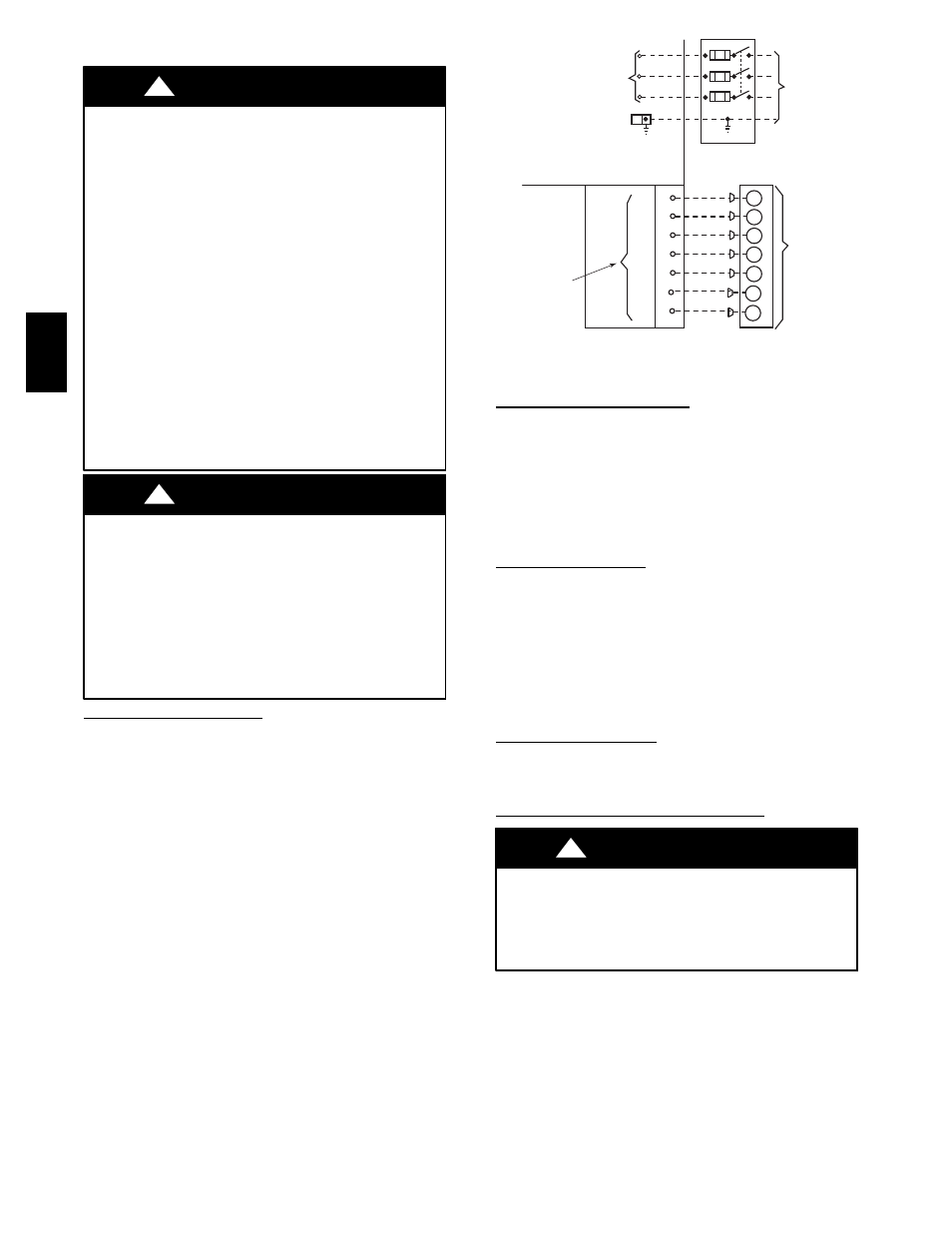
See unit wiring label (Fig. 12) and Fig. 10 for reference when
making high voltage connections. Proceed as follows to complete
the high--voltage connections to the unit.
1. Run the high--voltage (L1, L2, L3) and ground lead into the
control box.
2. Connect ground lead to chassis ground connection.
3. Locate the black, yellow and blue wires connected to the
line side of the terminal block.
4. Connect field L1 to black wire.
5. Connect field wire L2 to yellow wire.
6. Connect field wire L3 to blue wire.
POWER
SUPPLY
FIELD-SUPPLIED
FUSED DISCONNECT
HIGH VOLTAGE
POWER LEADS
(SEE UNIT WIRING
LABEL)
EQUIP GR
CONTROL BOX
W1
Y
G
R
C
THERMOSTAT
(TYPICAL)
W2
O
SPLICE BOX
LOW-VOLTAGE
TERMINAL BOARD
(SEE UNIT)
WIRING LABEL
W2
W1
Y1
G
R
C
Y2
A09378
Fig. 10 -- High-- and Control--Voltage Connections
Control Voltage Connections
NOTE: Do not use any type of power--stealing thermostat. Unit
control problems may result.
Use no. 18 American Wire Gage (AWG) color--coded, insulated
(35°C minimum) wires to make the control voltage connections
between the thermostat and the unit. If the thermostat is located
more than 100 ft (30.5 m) from the unit (as measured along the
control voltage wires), use no. 16 AWG color--coded, insulated
(35° C minimum) wires.
Standard Connections
Locate the low voltage terminal board in 24 volt splice box. See
Fig. 10 for connection diagram. Run the low--voltage leads from
the thermostat, through the control wiring inlet hole grommet (Fig.
3 and 4), and into the low--voltage splice box. Provide a drip loop
before running wires through panel. Secure and strain relief all
wires so that they do not interfere with operation of unit.
If an accessory electric heater is installed, low voltage leads from
heater must be connected to low voltage terminal board W1 and C
terminals.
Transformer Protection
The transformer is protected by a 24 volt circuit breaker. If an
overload or short is present, correct overload condition and reset 24
volt circuit breaker.
Special Procedures for 420--v Operation
ELECTRICAL SHOCK HAZARD
Failure to follow this warning could result in personal injury
or death.
Before installing or servicing system, always turn off main
power to system and install lockout tag.
!
WARNING
The transformer in the unit has two taps, 380 and 415 volts. For
power supplies above 400 volts, the transformer must be connected
to the 415 volt tap. With power off, disconnect blue wire from
transformer splice connection and connect black wire from
transformer to splice connection. Insulate unused blue transformer
tap. See transformer label. During unit start--up, check secondary
voltage to ensure that a minimum of 20 volts is available during
unit operation, and that voltage does not exceed 29 volts while unit
is off.
50J
Z
--
A