Step 2 — start--up adjustments, Checking and adjusting refrigerant charge, 50j z -- a – Carrier 50JZ-A User Manual
Page 14
14
5. Charge unit with Puron (R--410A) refrigerant, using an
electronic scale. Refer to unit rating plate for required
charge.
Step 2 — Start--Up Adjustments
Complete the required procedures given in the Pre--Start--Up
section before starting the unit. Do not jumper any safety devices
when operating the unit. Do not operate the unit in Cooling mode
when the outdoor temperature is below 40_F (4_C) (unless
accessory low--ambient kit is installed).
IMPORTANT: Three--phase, scroll compressors are direction
oriented. Unit must be checked to ensure proper compressor
3--phase power lead orientation. If not corrected within 5 minutes,
the internal protector will shut off the compressor. The 3--phase
power leads to the unit must be reversed to correct rotation. When
turning backwards, the difference between compressor suction and
discharge pressures may be minimal
Checking and Adjusting Refrigerant Charge
The refrigerant system is fully charged with Puron (R--410A)
refrigerant and is tested and factory sealed.
NOTE:
Adjustment of the refrigerant charge is not required
unless the unit is suspected of not having the proper Puron
(R--410A) charge.
A superheat charging chart is attached to the inside of the
compressor access panel (see Fig. 18). The chart includes the
required suction line temperature at given suction line pressures
and outdoor ambient temperatures.
An accurate thermocouple-- or thermistor--type thermometer, and a
gauge manifold are required when using the superheat charging
method for evaluating the unit charge. Do not use mercury or small
dial--type thermometers because they are not adequate for this type
of measurement.
NOTE: Allow system to operate for a minimum of 15 minutes
before checking or adjusting refrigerant charge.
IMPORTANT:
When evaluating the refrigerant charge, an
indicated adjustment to the specified factory charge must always be
very minimal. If a substantial adjustment is indicated, an abnormal
condition exists somewhere in the cooling system, such as
insufficient airflow across either coil or both coils.
Proceed as follows:
1. Remove cap from low pressure service fitting.
2. Using hoses with valve core depressors, attach low pressure
gauge hose to low pressure service fitting.
3. Start the unit in cooling mode and let run until system
pressures stabilize.
4. Measure and record the following:
a. Outdoor ambient--air temperature (°C) db.
b. Evaporator inlet--air temperature (°C) wb.
c. Suction--tube temperature (°C) at low--side service
fitting.
d. Suction (low--side) pressure (kPA).
5. Using “Cooling Charging Tables” compare outdoor--air
temperature (°C) db with the entering evaporator air temper-
ature (°C) wb to determine desired superheat temperature.
(See Fig. 16).
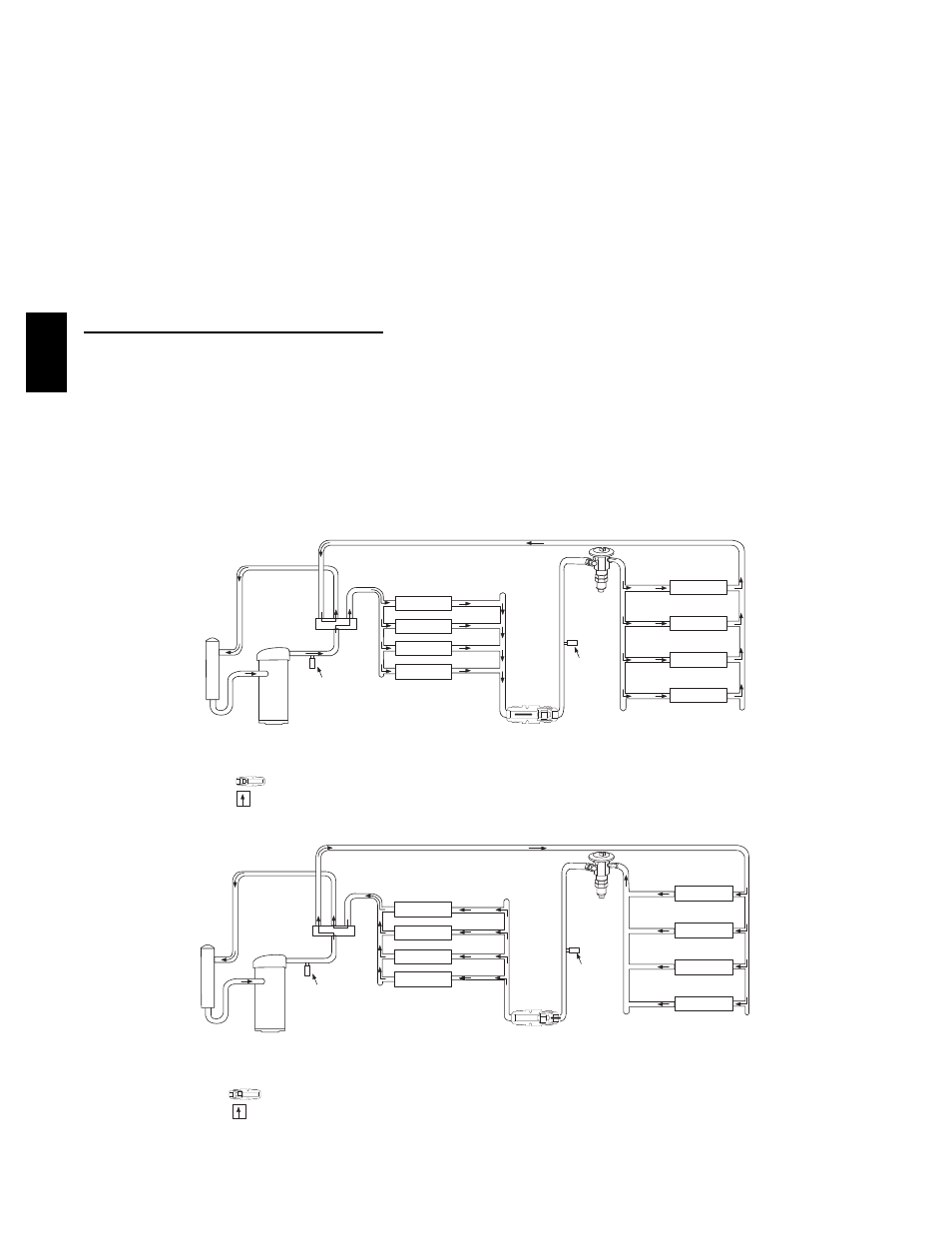
COMPRESSOR
ACCUMULATOR
OUTDOOR COIL
INDOOR COIL
LCS
LEGEND
HPS – High Pressure Switch
LCS – Loss of Charge Switch
Accurater
®
Metering De vice
Arrow indicates direction of flo
w
TXV in Metering
Position
Bypass
Position
HP S
C03011
Fig. 14 -- Typical Heat Pump Operation, Cooling Mode
COMPRESSOR
ACCUMULATOR
OUTDOOR COIL
INDOOR COIL
LCS
LEGEND
HPS – High Pressure Switch
LCS – Loss of Charge Switch
Accurater
®
Metering De vice
Arrow indicates direction of flo
w
Position
HP S
TXV in Bypass
Metering
Position
C03012
Fig. 15 -- Typical Heat Pump Operation, Heating Mode
50J
Z
--
A