CTEK Z4300U SkyRouter User Manual
Page 7
22 September 2009
4
Link - Multi-color (red/green). Indicates:
a) Status of IP connection
b) Type of transport (EDGE or GPRS)
Display Definition
Off
No Connection (IP address)
Green
Connection established on GPRS
Red
Connection established on EDGE
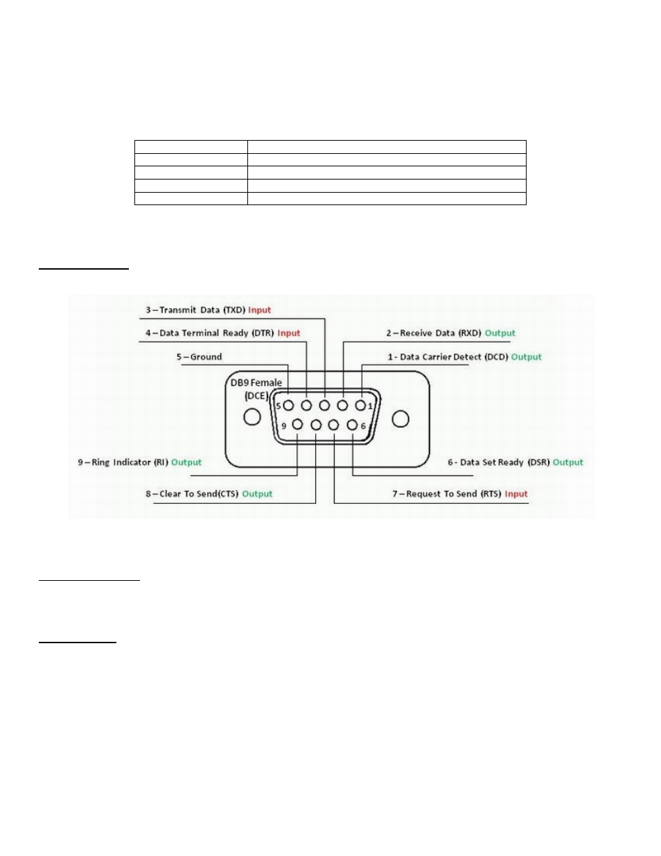
2.3 Connectors
RS232 Connector – This connector is a standard RS232 DCE interface. A straight-through RS232 cable should be used.
The RS232 connector pin out diagram is shown below.
Figure 2
Ethernet Connector
The Ethernet connector on the Z Series is a standard RJ45 connector with auto polarity sensing and can be used with
either a standard Ethernet cable or a reverse (cross over) Ethernet cable.
Terminal Block
Connector J1 supports four separate functions, power, relay contact closure detection, relay driver output, and auxiliary
serial port serial data. Contact closure pins 2 and 4 are shared with the auxiliary serial port. To option remove the circuit
board and locate 3-pin headers JP1 & JP2 behind the green connector. Facing the end of the board containing the green
connector JP1 and JP2 should have jumpers center to right to use the discrete I/O (Din, Dout), and JP1 and JP2 should
have jumpers center to left to use the auxiliary serial port. Auxiliary serial port parameters (baud, parity, etc.) are set using
the RS232 screen. From the factory the unit ships with the auxiliary serial port enabled.
.
The pin out configuration is as follows: