3 replacing the filter – Bio-Rad BioLogic Sample Loading Loops User Manual
Page 17
Reassembly
1. Hold the body of the sliding seal assembly in one hand. Insert, in order, the rubber ball,
the check valve guide, and spring into the hole in the center of the sliding seal housing.
Place the O-ring in the groove at the top of the housing. Screw the retainer cap onto the
body. (Ensure that the spring enters the large hole in the center of the cap.)
2. Insert the sliding seal assembly into the glass tube. The O-ring end of the sliding seal
assembly must be oriented in the same direction as the sample end legend on the
glass tube.
Caution: If the sliding seal assembly is inserted backwards, the DynaLoop can
overpressurize and break when reconnected to the system.
3. Insert the sample end cap into the sample end of the tube. (The sample end cap does
not have the white filter.)
4. Slide either end of the protective plastic jacket over the glass tube and screw it onto the
sample end cap.
5. Insert the buffer end cap (with the white filter), into the glass column and thread the end
cap into the plastic jacket. Hand tighten the assembly.
The DynaLoop is now ready for use. Be sure that the O-ring end of the sliding seal
assembly is oriented towards the sample end of the unit. Reconnect the sample and
buffer tubing, and purge air from the unit as described in Section 2.3, Installation.
4.3 Replacing the Filter
The filter is an assembly consisting of a filter and a distributor located at the buffer end
cap assembly. Replace the filter periodically. If the filter is plugged, you will observe
excessive pressures during loading and injection.
Removing Filter
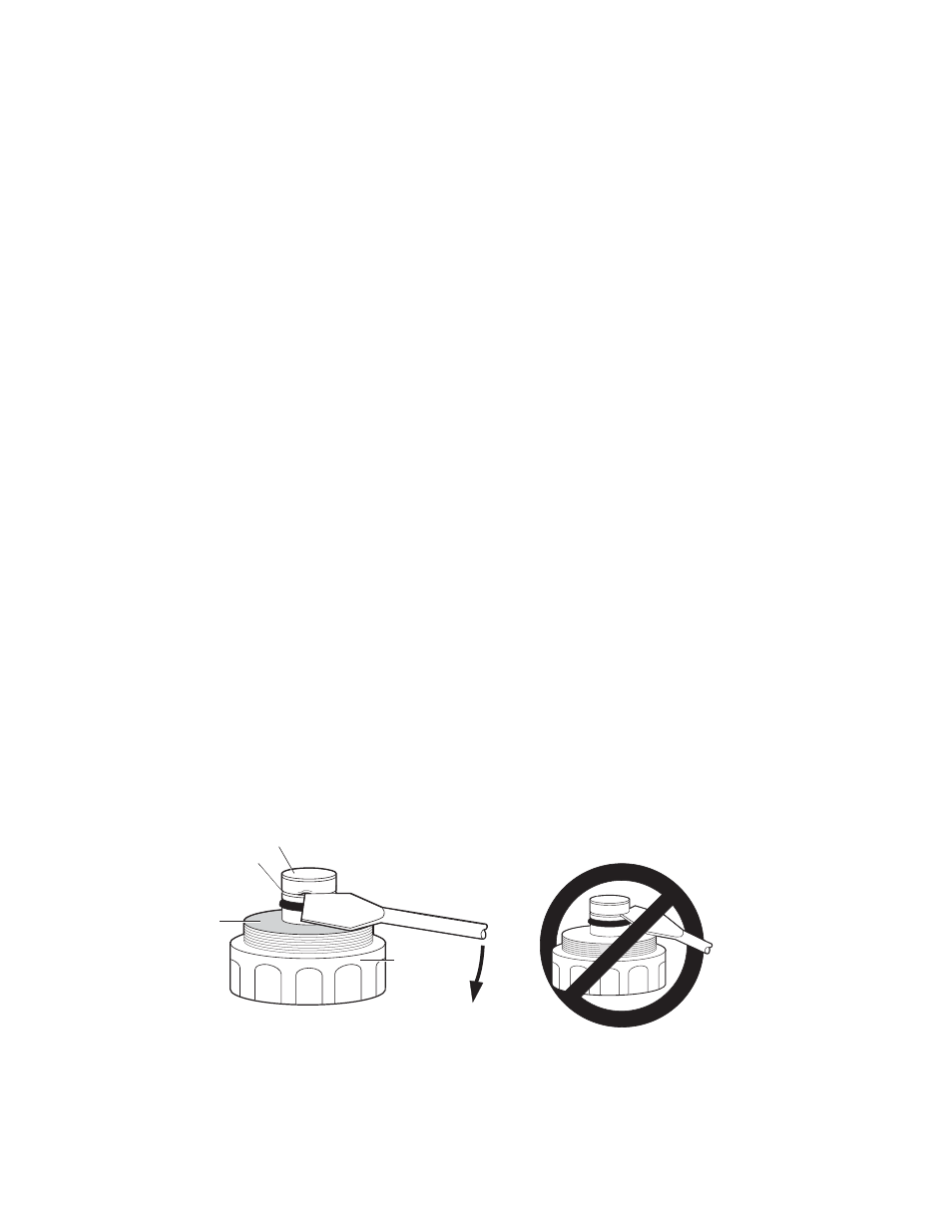
1. Disassemble the unit and remove the old filter. If you cannot pull off the filter with your
fingers, use a blade screwdriver. Lay the flat edge of the blade against the black plastic
part. Rotate the blade slightly to get the corner of the blade under the white skirt of the
filter cap. Pry off the filter by working the screwdriver in the gap between the filter and
the plastic lip. Lever the screwdriver against the large white threaded part of the end
cap, not the black plastic lip (see Figure 10).
Fig. 10. Removing the filter.
Buffer end cap
assembly
Filter
Gap
Use this surface
as a base to
lift filter
Pry
Downward
13