Bio-Rad BioLogic Sample Loading Loops User Manual
Page 11
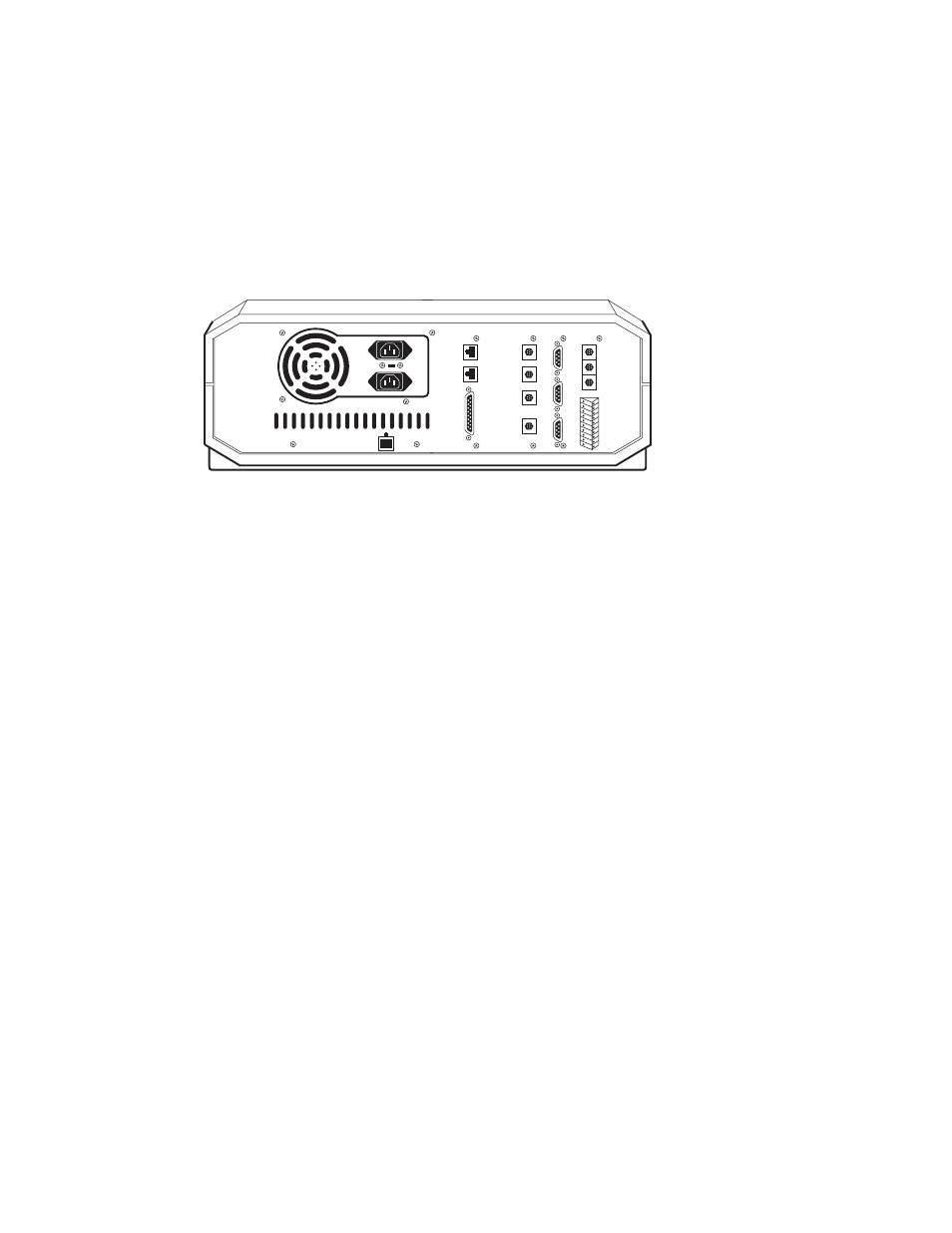
Electrical Connections (Model EP-1 Econo Pump)
1. Turn off the BioLogic DuoFlow controller and workstation.
2. Connect the EP-1 Econo pump to the BioLogic DuoFlow workstation using System
Cable 7 (mini-DIN to breakout, catalog number 731-8267). Plug the mini-DIN end of
System Cable 7 into the Econo pump rear connector labeled AUX. On the back of the
BioLogic DuoFlow workstation, connect the red wire to the auxiliary connector 6 (AUX
Pump) and connect the blue wire to the auxiliary connector 9 (GND) (Figure 7).
Fig. 7. Rear panel of BioLogic workstation and AUX connector.
Plumbing Connections
1. Use the fittings kit supplied with the EP-1 Econo pump and refer to the Econo pump
instruction manual for all peristaltic plumbing connections.
2. To connect the outlet end of the peristaltic pump tubing to port 2 on the injection valve,
use a luer to 1/4-28 adaptor (catalog number 732-0113).
Purge Lines
1. Disconnect the tubing from the column at the column inlet connection and redirect port 4
to a waste container.
2. Connect the EP-1 Econo pump inlet tube to a reservoir of buffer. Switch the injection
valve to the INJECT position. Set the BioLogic DuoFlow flow rate to 10 ml/min. Verify
that the DynaLoop fills with buffer.
Caution: The sliding seal must move toward the sample end of the DynaLoop. If the seal
moves toward the buffer end of the DynaLoop (the end with the white filter), stop the pump
immediately. The DynaLoop was installed backwards. Correct the plumbing configuration
before using the DynaLoop.
3. Manually start the EP-1 Econo pump. Buffer should flow from the pump to the drain
tube at port 1.
4. Continue running the BioLogic DuoFlow pump and the EP-1 Econo pump until the
DynaLoop and all tubing associated with the Econo pump are completely purged of air.
Flow into the waste containers should form a smooth stream free of bubbles. When the
sliding seal assembly contacts the sample end cap, the check valve inside the seal will
open allowing air and buffer to escape.
5. With both pumps still running, switch the injection valve to LOAD. Flow from the
peristaltic pump will move the sliding seal towards the buffer end of the DynaLoop.
Flow from the BioLogic DuoFlow pump will go through the injection valve directly to port
4 and then temporarily to waste.
INSTR
BUS
TEST
PORT
UV
CHART
COND
CHART
UV
OPTICS
COND
FLOWCELL
AUTOMATED VALVES
SOLONOID VALVES
1
2
3
4
5
6
AUX
1. Inject
2. n/c
3. n/c
4. n/c
5. FC Adv
6. AUX Pump
7. n/c
8. n/c
9. Gnd
UV
LAMP
7