Bio-Rad BioLogic Sample Loading Loops User Manual
Page 10
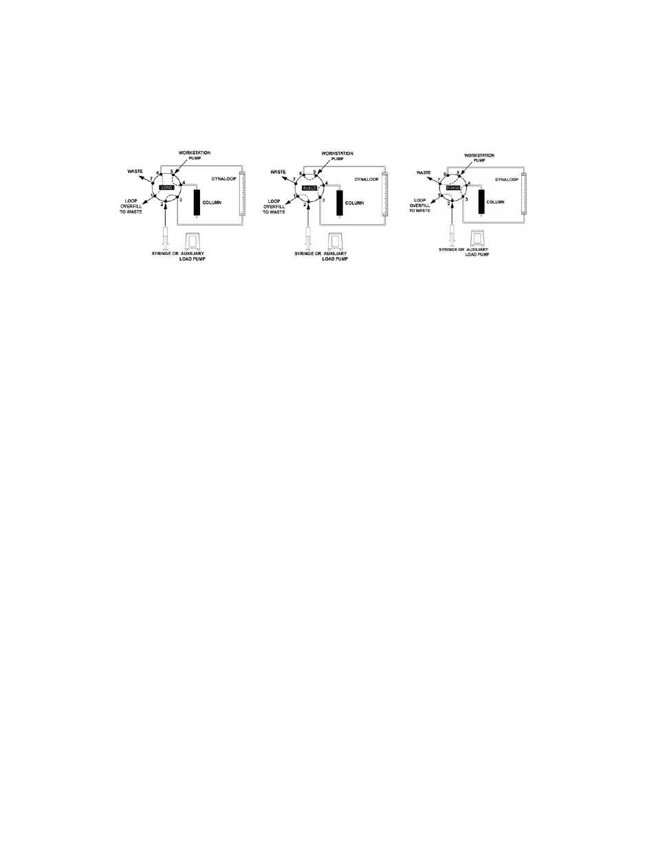
3. Connect the sample end of the DynaLoop to port 3 of the injection valve (Figure 6).
4. Connect the buffer end of the DynaLoop to port 6 of the injection valve (Figure 6).
Fig. 6. Injection valve positions.
Purge Lines
1. Disconnect the tubing from the column at the column inlet (port 4) and redirect port 4 to
a suitable waste container using a short piece of tubing.
2. Switch the injection valve to INJECT. Set the BioLogic DuoFlow pump flow rate to
10 ml/min. Verify that the DynaLoop fills with buffer.
Caution: The sliding seal must move toward the end of the DynaLoop designated as the
sample end. If the seal moves toward the buffer end of the DynaLoop (the end with the
white filter), stop the BioLogic DuoFlow pump immediately. The DynaLoop was installed
backwards. Correct the plumbing configuration before using the DynaLoop.
3. Continue the flow until the DynaLoop is completely purged of air. Flow into the waste
container should form a smooth stream free of bubbles. When the sliding seal assembly
contacts the sample end cap, the check valve allows air and buffer to flow out through
the DynaLoop sample delivery tube.
4. Use a syringe to deliver a couple of milliliters of buffer into the injection port (port 2) until
it flows smoothly from the drain tube outlet (port 1) (Figure 6).
5. With the pump still running, switch the injection valve to LOAD. Allow the pump to run
until the flow from the column connection tube makes a smooth stream free of bubbles
into the waste container.
6. Stop the BioLogic DuoFlow pump.
7. Reconnect the column inlet tubing to the column. The system is now ready for use.
Refer to Section 3, Using the DynaLoop, for applications information.
Peristaltic Pump Setup
There are three stages to installing the Bio-Rad
®
Model EP-1 Econo
™
pump or the
Econo gradient pump:
•
Electrical connections
•
Plumbing connections
•
Purging lines of air
6