Fasteners, Ratchet drive (8 row only), Finger pickup meter – Great Plains PT8030 V1013 Operator Manual User Manual
Page 38
36
Section 5 Maintenance and Lubrication
10/10/12
PT6030 and PT8030 Pull-Type Planter 401-032M-A
Great Plains Mfg., Inc.
2.
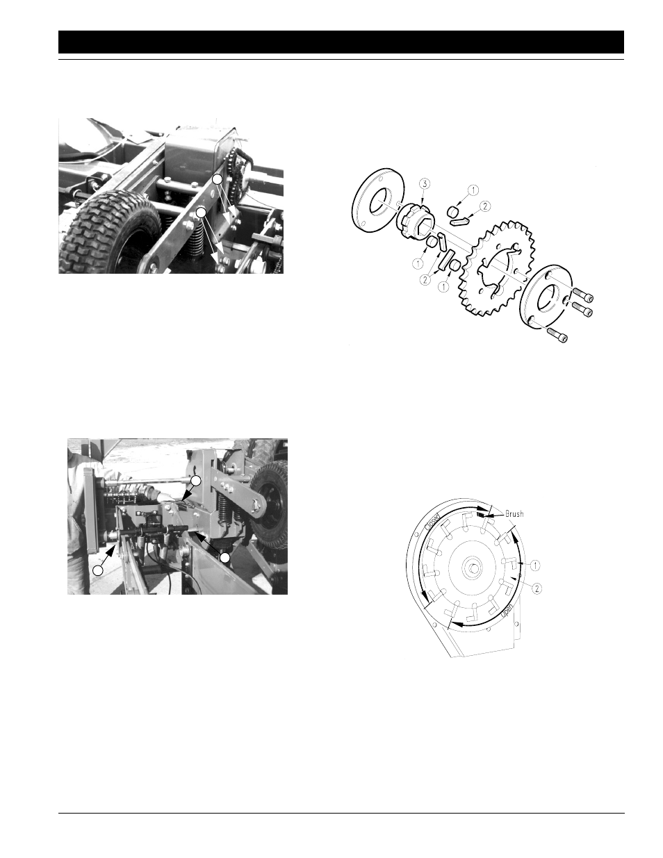
If the shafts are not aligned, adjust the contact-drive
tower. Loosen the mounting bolts (1) on both sides of
the tower. Adjust tower position until shafts are
aligned.
16849
1
1
Figure 5-4
Contact Drive Housing Adjustment
3.
Retighten tower mounting bolts. Slide coupler sleeve
over transmission-input shaft and re-insert cotter pin.
4.
Level the transmission-output shaft. Place a straight
edge across the 7-by-7-inch frame tube. Take a mea-
surement from the straight edge (1) down to the top of
the shaft (2). Repeat measurement at each row unit.
Measurements must be equal across the planter.
To level the shaft, loosen the shaft hanger bearings (3)
at each row unit. Adjust shaft until measurements are
equal across the planter.
16833
1
2
3
Figure 5-5
Leveling Transmission-Output Shaft
Fasteners
When working on the planter torque all bolts, screws and
nuts to the correct values listed on Torque Values Chart,
“Appendix” on page
52. Check latches and other fasten-
ers on the planter to prevent failures in the field.
Ratchet Drive (8 Row Only)
The ratchet assembly must operate freely and the springs
(1) must bring the dogs (2) back against the ratchet hub
(3).
Repack with grease annually.
15177
Figure 5-6
Ratchet Drive
Finger Pickup Meter
Inspect and repair the finger pickup meter by removing the
two bolts holding the meter to the hopper. Remove the
three bolts on the meter baffle to gain access to the finger
mechanism.
Rotate the meter input shaft by hand to check the fingers.
The fingers should be against the carrier plate in the area
shown closed and raised in the area shown open in Figure
5-7.
Figure 5-7
Finger Raised/Location of Brush
12353