Marker width, Tire scraper, Meter drive adjustments – Great Plains PT8030 V1013 Operator Manual User Manual
Page 32: Check vertical alignment, Check horizontal alignment
30
Section 3 Adjustments
10/10/12
PT6030 and PT8030 Pull-Type Planter 401-032M-A
Great Plains Mfg., Inc.
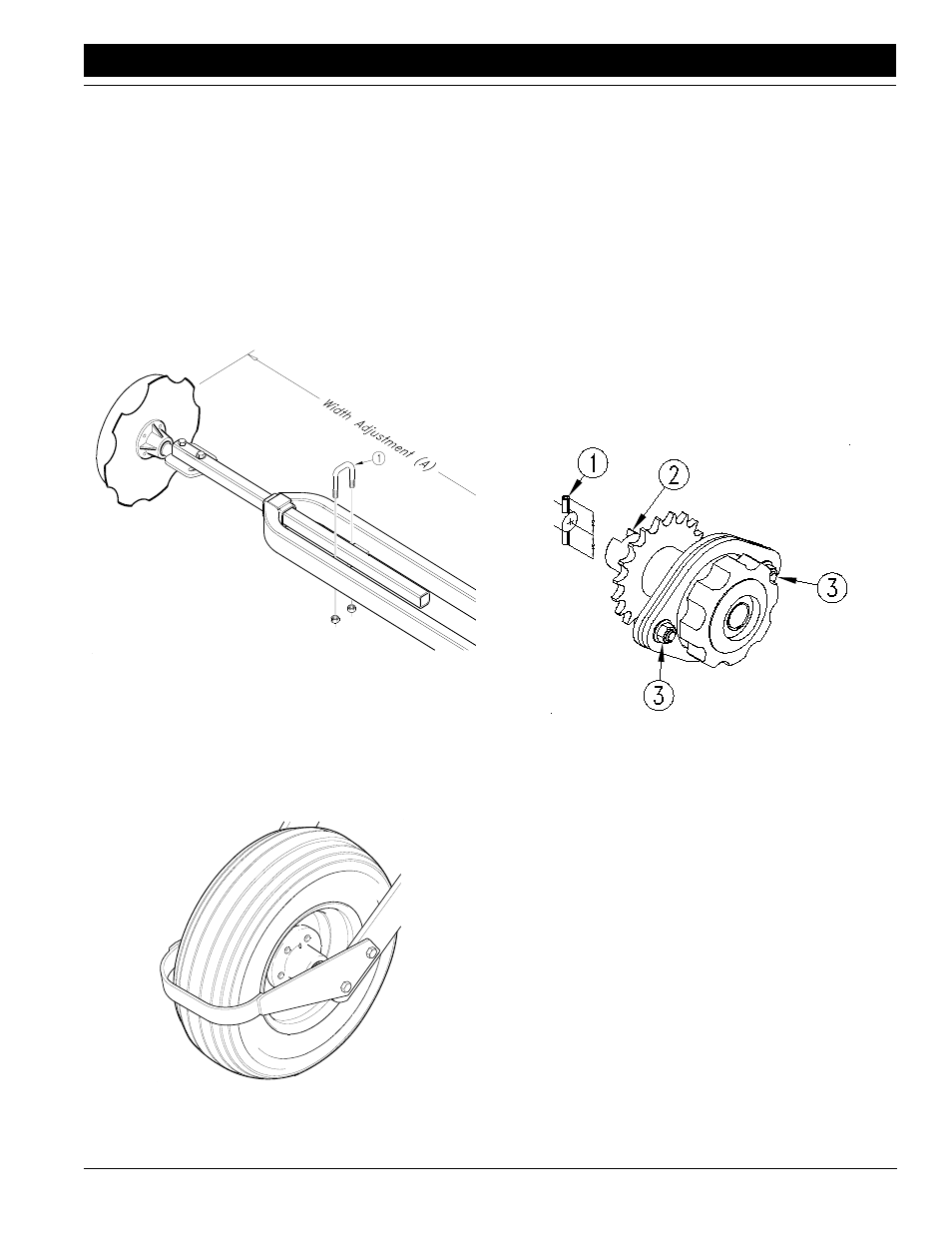
Marker Width
Refer to Figure 3-19.
To adjust marker width, loosen the marker tube u-bolt (1)
and slide it in or out to the desired width. After adjusting,
retighten the u-bolt.
Dimension (A) is measured from the center line of the
planting unit to the marker disk. The dimensions provided
are approximate. After adjusting, field check the actual di-
mension.
For 6-row, 30 inch rows, A = 180 inches.
For 8-row, 30 inch rows, A = 240 inches.
Figure 3-19
Marker Disk Adjustment
15835
Tire Scraper
In some soil types, you may need to use optional tire
scrapers. The scrapers prevent excess mud from building
up on the transport tires so the contract-drive tire can op-
erate properly. Adjust the scraper so it does not contact
the tire. See Figure 3-20.
Figure 3-20
Tire Scraper
15027
Meter Drive Adjustments
The alignment between the meter clutch and the input
shaft on both the seed and chemical hoppers is important.
If there is misalignment, the meters will not function prop-
erly. Excessive wear and damage can also occur to the
meter housings. When replacing the meters, check the
vertical and horizontal alignment.
Check Vertical Alignment
Refer to Figure 3-21.
1.
Latch the hopper into place on the support.
2.
Check that the roll pin (1) in the end of the input shaft
is centered so equal amounts of the roll pin protrude
from both sides of the shaft.
3.
Rotate the input shaft so the roll pin is vertical.
4.
Rotate the drive coupler (2) so the slots are vertical.
5.
Release the clutch to engage the drive coupler with
the input shaft.
16869
Figure 3-21
Vertical Alignment
6.
If the alignment is correct, the coupler will engage with
the shaft freely and the roll pin will extend equally on
each side of the coupler. If not, adjust alignment as ex-
plained under Meter Drive Alignment, this page.
Check Horizontal Alignment
1.
Latch the hopper into place on the support.
2.
Check that the roll pin in the end of the input shaft is
centered so equal amounts of the roll pin protrude
from both sides of the shaft.
3.
Rotate the input shaft so the roll pin is horizontal.
4.
Rotate the drive coupler so the slots are horizontal.
5.
Release the clutch to engage the drive coupler with
the input shaft.
6.
If the alignment is correct, the coupler will engage with
the shaft freely and the roll pin will extend equally on
each side of the coupler. If not, adjust alignment as ex-
plained under Meter Drive Alignment, this page.