Planting rate, Transmission adjustment, To-1 drive reduction – Great Plains PT8030 V1013 Operator Manual User Manual
Page 17: Checking planting population, Section 3 adjustments
15
Section 3 Adjustments
PT6030 and PT8030 Pull-Type Planter 401-032M-A
10/10/12
Great Plains Mfg., Inc.
Section 3
Adjustments
Checking Planting Population
After setting the transmission or contact-drive reduction,
always field check the planting population as follows.
1.
Release spring pressure on opener disks and wheels.
2.
Tie up closing disks and wheels to hopper support us-
ing a chain or heavy wire. Pin up optional Seed-Lok
wheels
3.
Adjust the planting depth to a shallow setting.
4.
Plant at a normal speed for a short distance.
5.
For 30-inch rows, measure 17 feet 6 inches (one-thou-
sandth of an acre.)
6.
Count the number of seeds in one row over the mea-
sured distance.
7.
Multiply the number of seeds counted by 1000. This
gives you total population.
Example
• 30-inch row spacing
• Measure 17 feet 6 inches
• 24 seeds over measured distance in one row
24 X1000 = 24,000 plant population per acre
If the planting population is significantly different than de-
sired, make the following checks.
• Double check the sprocket combination in the trans-
mission. Refer to the “Planting Rates for Finger
Pickup Corn Meters” on page
16.
• Check air pressure in the gauge-wheel tires. Refer to
Tire Inflation Chart, “Appendix” on page
52.
• Check for meter malfunction or excessive contact-
drive-wheel slippage. Refer to “Section 4 Trouble-
shooting” on page
Planting Rate
Transmission Adjustment
To change planting population, change the sprocket com-
bination on the transmission.
1.
Refer to “Planting Rates for Finger Pickup Corn
Meters” on page
16 or “Planting Rates for Brush
17 for the proper sprocket combina-
tion for your desired planting population.
2.
Remove the cover from the transmission by loosening
the knob on the cover.
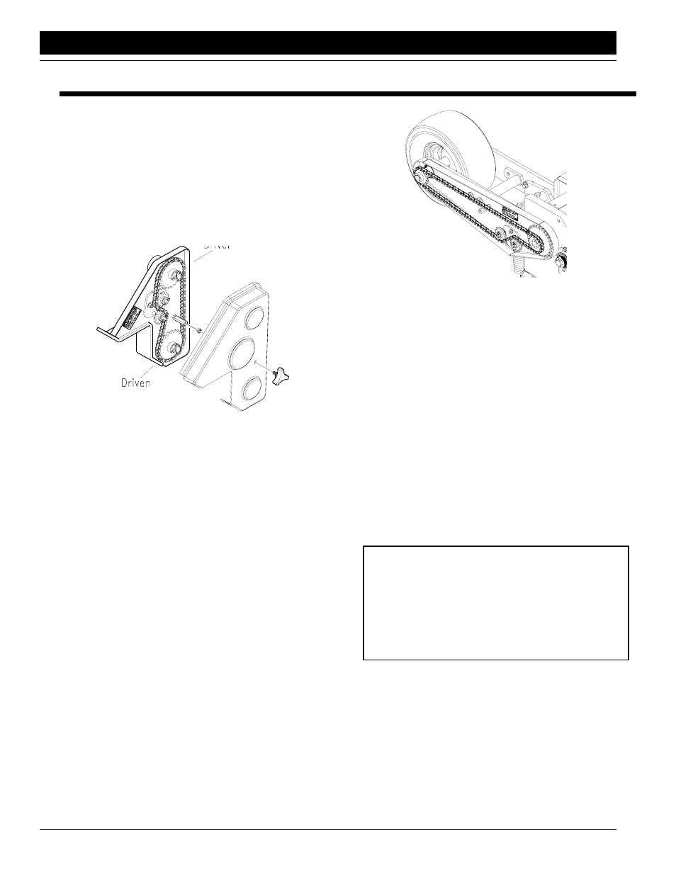
Figure 3-1
Planter Transmission
16861
3.
Loosen the carriage bolt and flange nut on the idler
plate. Rotate the idler plate to move the idlers out of
the chain.
4.
Remove the chain. Remove sprockets currently on
transmission shafts.
5.
Find the correct sprockets on the storage brackets
and place on the transmission shafts.
NOTE: When not in use, store all extra sprockets on the
storage bracket.
6.
Place the sprockets on the drive/driven shafts.
7.
Re-route chain over idlers and sprockets.
8.
Turn the idler plate counter-clockwise to take up chain
slack. Chain should have a maximum of 1/4-inch
slack.
9.
Retighten the carriage bolt and flange nut to secure
idler plate.
10. Replace the transmission cover and hand tighten the
knob.
16863
Figure 3-2
2-to-1 Drive Reduction
2-to-1 Drive Reduction
The 15/28 tooth drive sprocket located on the inner side of
the contact drive wheel assembly will give you a 2-to-1
drive reduction and reduce planting rates by about one-
half.
NOTE: After each sprocket combination adjustment, make
a field check to be sure you are planting at the desired
rate.