Marker adjustments, Folding speed, Disk adjustments – Great Plains PT8030 V1013 Operator Manual User Manual
Page 31: Disk angle, Direction of cut, Danger, Warning
29
Section 3 Adjustments
PT6030 and PT8030 Pull-Type Planter 401-032M-A
10/10/12
Great Plains Mfg., Inc.
Marker Adjustments
Folding Speed
!
DANGER!
Never allow anyone near the planter when cycling the markers.
Excessive travel speed of the markers can be dangerous and/or
damage the marker assembly.The flow controls should be prop-
erly adjusted before the marker assembly is first put into use.
!
WARNING!
Escaping fluid under pressure can have sufficient force to pene-
trate the skin. Check all hydraulic lines and houses before ap-
plying pressure. Fluid escaping from a very small hole can be
almost invisible. Use paper or cardboard, not body parts, to
check for suspected leaks. If injured, seek medical assistance
form a doctor that is familiar with this type of injury. Foreign
fluids in the tissue must be surgically removed within a few
hours or gangrene will result.
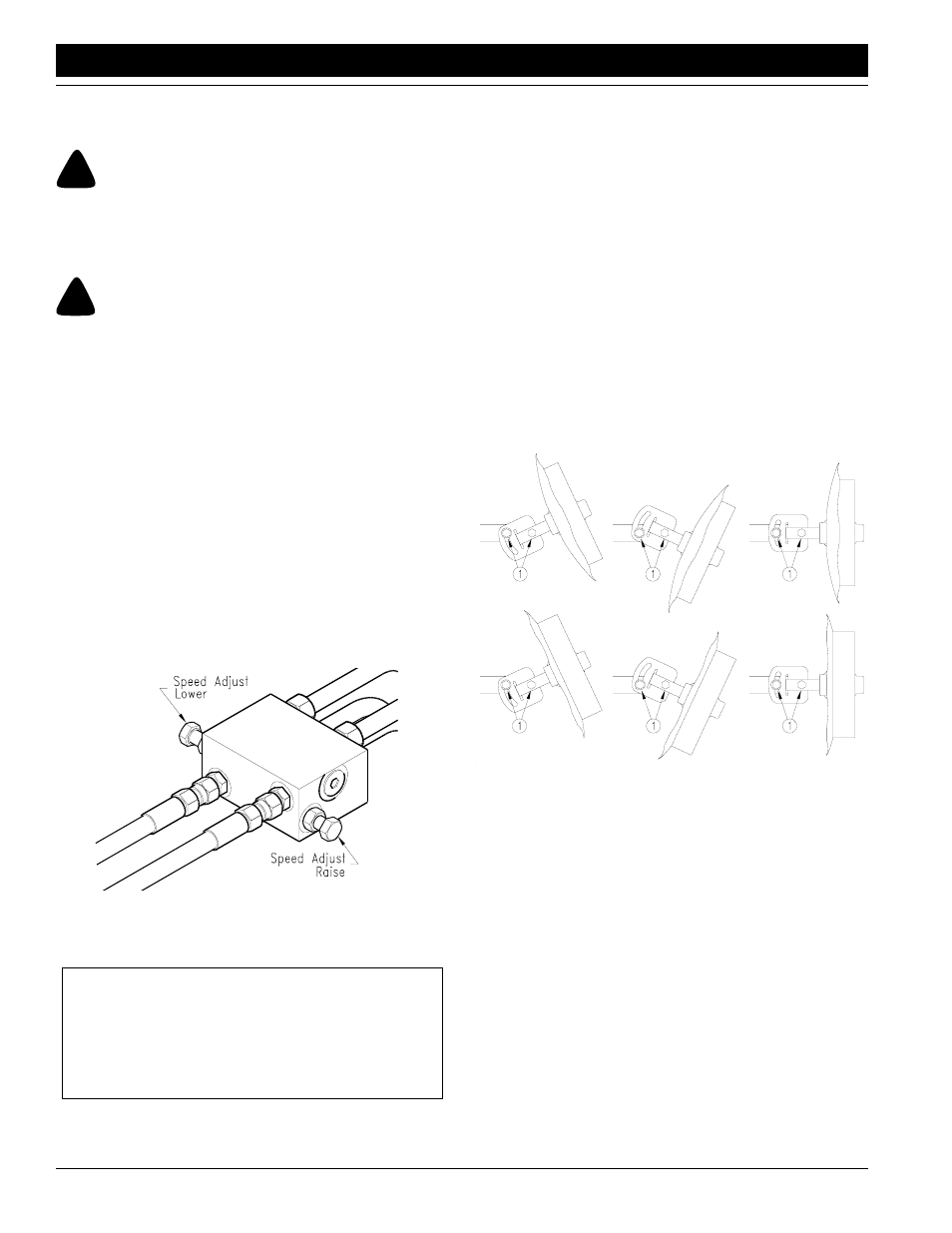
The marker hydraulic system is equipped with needle
valves to control how fast each marker operates. The nee-
dle valves are built into the sequence valve body. There
are two hex adjustment heads, one for controlling marker
speed up and one for controlling marker speed down.
Excessive folding speeds can cause marker damage.
With the tractor engine at an operating rpm, loosen jam
nut and adjust the needle valve to limit the marker to a safe
operating speed. Make sure all adjustments are made
with warm oil. Fold the marker up and down a few times
and recheck for pinching and kinking of hoses.
Figure 3-17
Flow Control Raise/Lower
15029
IMPORTANT: JIC fittings do not require high torque.
JIC and O-Ring fittings do not require sealant. Al-
ways use liquid pipe sealant when adding or replac-
ing pipe thread fittings. To avoid possible danger of
cracking hydraulic fittings from over tightening, do not
use plastic sealant tape.
Disk Adjustments
The aggressiveness and the mark left by the disk may be
changed by two methods.
1.
Disk Angle
To change the angle of cut, loosen the two bolts (1),
rotate the disk assembly and retighten.
2.
Direction of Cut
The disk may be mounted to throw dirt either in or out
which will give different marks in different soil condi-
tions. To change the direction of cut:
a.
Reverse the blade and depth band by remounting
the four lug bolts on the disk hub.
b.
Reverse the angle of the assemble by removing
the adjustment bolts (2) and turning the spindle
assembly one half turn. Re-install and tighten all
bolts.
15834
Figure 3-18
Marker Disk Adjustments