Section 5 maintenance and lubrication, Install cylinder stops, Replacing shear pins – Great Plains PT8030 V1013 Operator Manual User Manual
Page 37: Shaft alignment, And “section 5 maintenance and, Caution
35
Section 5 Maintenance and Lubrication
PT6030 and PT8030 Pull-Type Planter 401-032M-A
10/10/12
Great Plains Mfg., Inc.
Section 5
Maintenance and Lubrication
Install Cylinder Stops
!
CAUTION!
Always install cylinder stops when working around or near
planter.
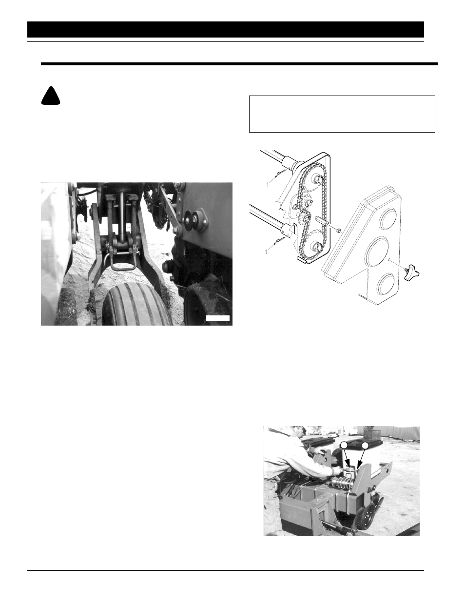
Install cylinder stops whenever the planter is raised for
maintenance. To install the stops, refer to Figure 5-1.
Raise planter to transport position with tractor remote cyl-
inder operating lever. Pivot cylinder stop into position on
wheel module cylinder rods. Lower to stop. Install bent pin
and secure with cotter pin.
Figure 5-1
Cylinder Stop
16889
Before lowering the planter, remove bent pin, pivot cylin-
der stop off of cylinder, and re-install bent pin.
Replacing Shear Pins
The cotter pins (1) that connect the transmission-input and
-output shafts to the transmission will shear when an ex-
cessive load is put on the shafts.
Infrequent or improper lubrication causes binding of mov-
ing parts within the planter. This binding will cause the cot-
ter pins to shear, thus preventing breakage of planter
parts.
Check for binding by turning the drive shaft with all seed
hoppers installed and seed meters engaged. If the drive
shaft is hard to turn, disengage one seed-meter clutch at a
time to find the problem clutch.
Improper shaft alignment can also cause pins to shear.
Refer to Shaft Alignment, this page, to check shaft align-
ment.
When the drill shaft can be turned freely by hand, replace
the cotter pin.
IMPORTANT: Only replace the cotter pins with cotter
pins of the same size. Do not replace with other type
pins.
Figure 5-2
Transmission Cotter Pins & Shear Pins
16862
Shaft Alignment
Improper alignment of the transmission-input and -output
shafts can cause pins to shear. To function properly, the
shafts must be aligned and level. If the planter is consis-
tently shearing pins, follow these steps to check and adjust
the shafts.
1.
Check that the transmission-input shaft (1) and trans-
mission shaft (2) are aligned. Remove cotter pin from
coupler sleeve. Pull the coupler sleeve back and ob-
serve the shafts.
16832
2
1
Figure 5-3
Transmission-Input Shaft Alignment