5313-5315 wings, 5317-5323 wings, 5313-5315 wings 5317-5323 wings – Great Plains TC5319 (S/N A1420X+) Assembly Manual User Manual
Page 22
18
TC5109-5323
Great Plains Manufacturing, Inc.
566-224Q-ENG
03/06/2014
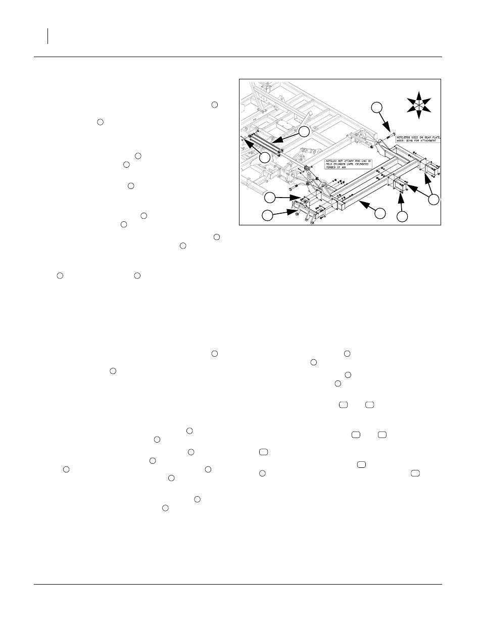
5313-5315 Wings
Refer to Figure 12
65. Carefully align holes in wing frame LH and RH
with
holes on center frame hinges. Secure with 1 1/4 x 8
Gr. 8 hex bolt
and 1 1/4 top lock nut.
Note: Tighten bolts snug but do not over-tighten as wings
need to pivot freely.
66. Attach wing gang mount
to front wing frame plates
with 3/4 x 2 hex bolts
, 3/4 lock washers and 3/4 hex
nuts.
Note: Wing shank mounts
are only used on some mod-
els, see machine and attachment layout drawings in
Appendix for proper placement.
67. Install wing shank mounts
to wing frame plate with
3/4 x 2 1/2 hex bolts
, 3/4 lock washers and 3/4 nuts.
68. Attach base end of the 4 x 30 x 2 fold cylinders
to
center fold bracket with 1 x 3 3/8 pins
, 1.5 x 1.0
x.075 machine washer and 3/16 x 2 cotter pin.
Note: Do not attach rod end of the 4 x 30 x 2 fold cylinders
to wing cylinder lug
until fold cylinders have
been purged of air, See “Purging Hydraulic Sys-
tem” on page 28.
69. Tighten all bolts to specs, See “Torque Values Chart”
5317-5323 Wings
Refer to Figure 13
70. Carefully align holes in wing frame LH and RH
with holes on center frame hinges. Secure with 1 1/4
x 8 Gr. 8 hex bolt
and 1 1/4 top lock nut.
Note: Tighten bolts snug but do not over-tighten as
wings need to pivot freely. When wing frame is
attached to center frame, set stands (if available)
under outer part of wings to hold wings level for
rest of assembly.
71. Attach lower hole of cylinder mount bar
to ears of
wing frame with 1 x 4 hex bolt
, and 1 lock nut.
72. Attach upper hole of cylinder bar mount
to one
end of wheel arm turnbuckle
with 1 x 3 1/2 hex
bolt
, two 1.5 x 1.0 x.075 machine washers
(one
in each side of cylinder bar mount
), secure with 1
lock nut.
73. Attach other end of wheel arm turnbuckle
to wing
frame ear with 1 x 3 1/2 hex bolt
, two 1.5 x 1.0
x.075 machine washers
(one in each side of cylin-
der bar mount
), secure and 1 lock nut.
74. Attach wing gang mount
to front wing frame plates
with 3/4 x 2 hex bolts
, 3/4 lock washers and 3/4
hex nuts.
Note: Wing shank mounts
and
are only used on
some models, see machine and attachment layout
drawings in Appendix for proper placement.
75. Install wing shank mounts
and
(model 5323
only) to wing frame plate with 3/4 x 2 1/2 hex bolts
, 3/4 lock washers and 3/4 nuts.
76. Attach the wing lift cylinders
to cylinder bar mount
and ear on torque tube with 1 x 3 3/8 pins
, 1.5 x
1.0 x.075 machine washer and 3/16 x 2 cotter pin.
77. Tighten all bolts to specs, See “Torque Values
Figure 12
5313-5315 Wings
42682
1
5
2
6
U
D
F
B
L
R
3
8
4
7
1
2
3
4
5
5
6
7
8
7
5
1
2
3
7
3
4
5
6
3
4
5
6
3
8
9
10
11
10
11
12
13
3
14
- TC5323 (S/N A1420X+) Assembly Manual TC5321 (S/N A1420X+) Assembly Manual TC5317 (S/N A1420X+) Assembly Manual TC5315 (S/N A1420X+) Assembly Manual TC5313 (S/N A1420X+) Assembly Manual TC5115 (S/N A1420X+) Assembly Manual TC5113 (S/N A1420X+) Assembly Manual TC5111 (S/N A1420X+) Assembly Manual TC5109 (S/N A1420X+) Assembly Manual