Appendix b - initial setup, Seed monitor console installation, Radar calibration – Great Plains YP2425A Operator Manual User Manual
Page 155
2014-02-10
401-626M
Great Plains Manufacturing, Inc.
151
Appendix B - Initial Setup
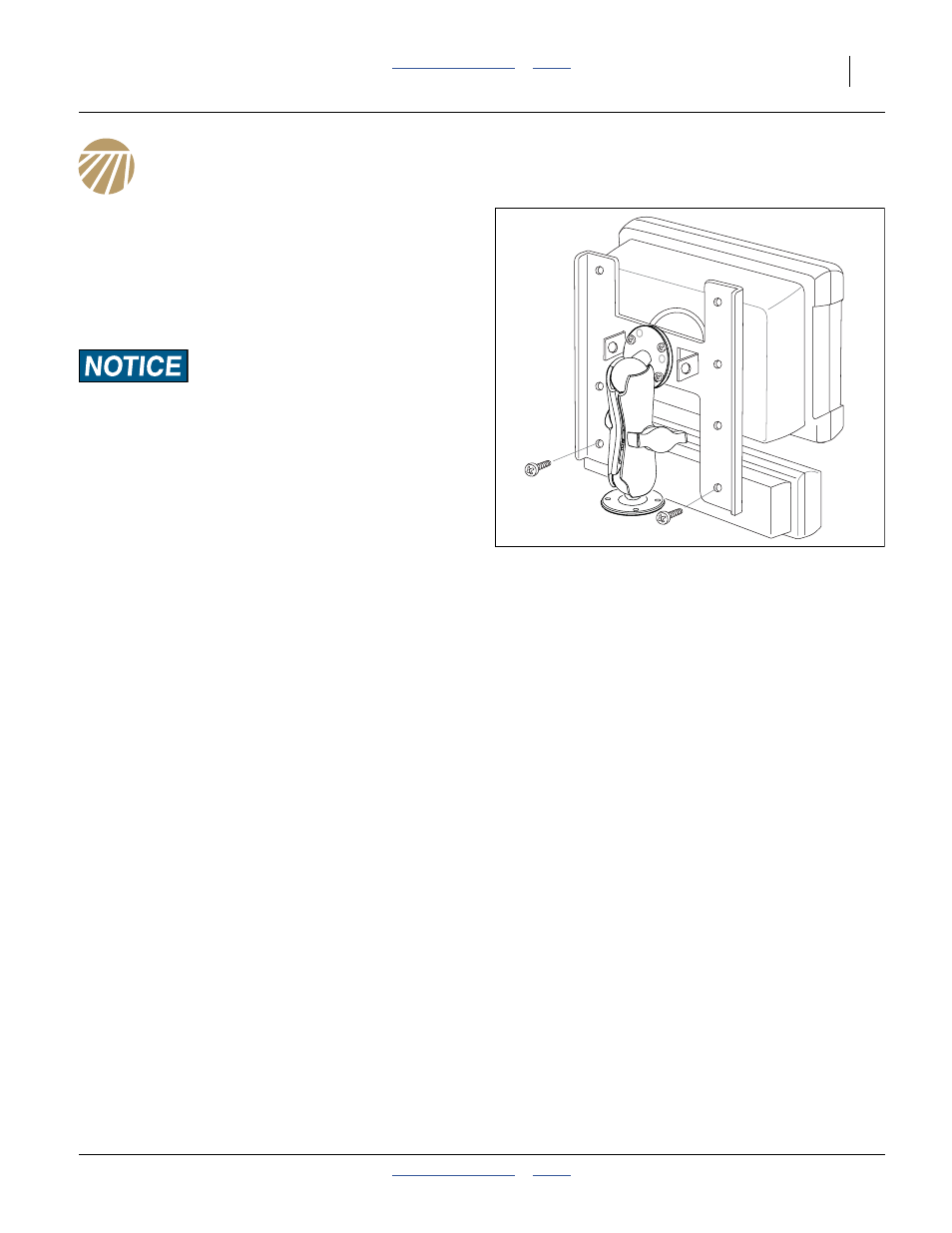
Seed Monitor Console Installation
The Planter Planter’s standard seed monitor system
includes a virtual terminal and switch panel that must be
mounted in the tractor cab. As supplied by
DICKEY-john
®
, the kit includes a flat bracket for the
modules, and a ball swivel for mounting the bracket in the
tractor.
Mount the modules so that they are easy to monitor during
planting, but do not interfere with safe operation of the tractor
in the field or on public roads.
The ball swivel includes four 10-32 screws. You or your
dealer must provide the mounting holes for the screws.
Your dealer may have alternate suction cup or clamping
brackets available if you prefer to avoid drilling holes.
Refer to the included DICKEY-john
®
manual for harness
connections.
Radar Calibration
At the first opportunity to operate the planter in the field
(with or without planting), the radar component of the
seed monitor needs to be calibrated. The seed monitor
manual describes the procedure.
Note: The planter must be in the lowered/field position for
this calibration. The angle of the sensor changes
when the planter is raised, and readings during
planting will be incorrect if calibrated in the raised
configuration.
Note: Due to this angle change, seed monitor speed
readings will not match tractor speedometer
reading during transport.
Figure 150
Terminal and Switch Panel
26303