Transport lower, Unfolding – Great Plains 3S-3000HDF Operator Manual v1 User Manual
Page 33
Great Plains Manufacturing, Inc.
Operating Instructions
29
2014-07-01
195-441M
Transport Lower
1.
Park tractor and drill on level ground with tractor
transmission in Park. Be aware of clearance needed
to unfold drill.
2.
If the Two Outlet conversion kit is installed, confirm
that the selector valve, located near the hitch, is set
for Transport Lift operations. See “Lift Selector
Valve Operation” on page 42.
3.
Slowly extended the Transport Lift circuit lever until
all three Transport Lift circuit cylinders are fully
extended (2 at transport wheels; 1 at transport hooks
on tongue). Set circuit lever to off or neutral (not
float).
Refer to Figure 20
4.
Rotate cylinder lock channels down and forward off
transport lift cylinders.
FigureSpacer
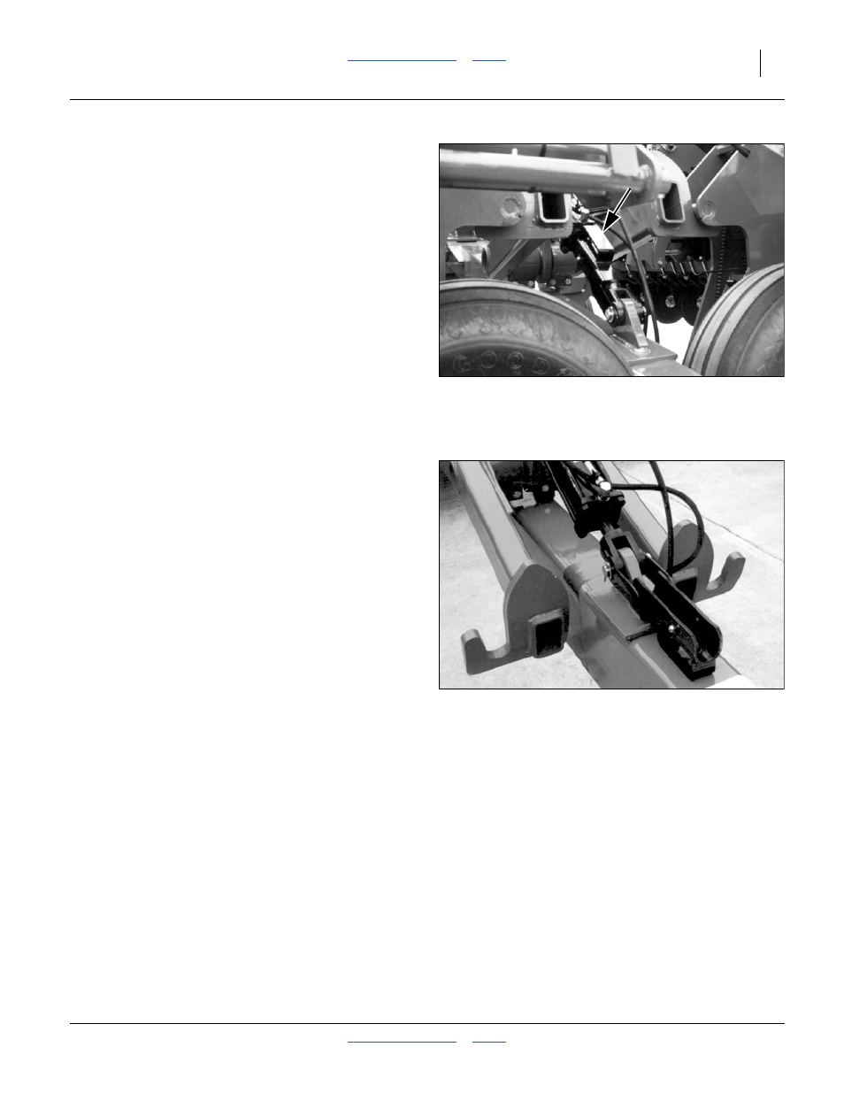
Refer to Figure 21
5.
Rotate cylinder lock channel up and forward off front
box lift cylinder.
6.
Slowly reverse the lift circuit lever and begin lowering
the drill. Keep the circuit engaged until all three
cylinders are completely retracted. Set circuit to off
or neutral.
The drill is now ready for unfolding.
Unfolding
Drill must be lowered from transport lift prior to unfolding.
See “Lowering Drill (Transport Lift)” on page 28.
1.
Verify that the site has clearance needed to unfold
drill.
2.
If markers are installed, set Marker/Fold valve at
hitch to Fold.
Refer to Figure 23
3.
Verify that the opener sub-frames are still raised and
locked up (handles in ROAD position).
4.
Slowly supply oil to base end of fold circuit. Unfold
wing frames by completely extending fold cylinders.
FigureSpacer
Figure 21
Front Box Lift Cylinder
Locked for Transport
15631
FigureSpacer
Figure 22
Front Box Lift Cylinder
in Field Configuration
15553