Gauge wheel adjustments, Gauge wheel tension, Planting on beds – Great Plains 3P4025AH Operator Manual User Manual
Page 49: Ground drive adjustments, Setting ground drive
Great Plains Manufacturing, Inc.
Adjustments
45
2014-07-29
411-099M
Gauge Wheel Adjustments
The gauge wheels serve three functions:
Refer to Figure 33
1.
Regardless of meter drive type, the gauge wheels
each establish the heights of their respective
sections, (or wings on 2-drive models). A
spring-loaded yoke
assembly provides some
flexibility over rocks and uneven ground. See
“Gauge Wheel Tension” to set this spring.
2.
Each gauge wheel contributes drive power for its
respective row unit mechanisms (on 3-drive models
these systems are fully independent).
3.
The gauge wheels control the planting rate at the
meters, via three sprocket setup positions. See
“Setting Seed Rate” on page 41.
Gauge Wheel Tension
Refer to Figure 33
Before performing this step, the planter center section
and wings must be level and aligned, and the tool bar
height must be set to 26 inches (66 cm). If these steps
have not been performed, See “Leveling the Planter”
on page 19.
As the gauge wheel tire wears, this adjustment may need
periodic attention.
The planter must be on firm, level ground for this step
(which may be performed when the planter leveling is
done). The planter must be unfolded.
1.
Raise the planter so that the gauge wheels are just
off the ground.
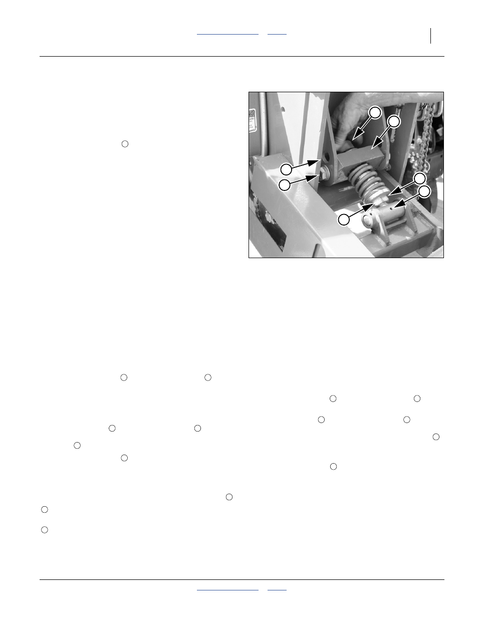
2.
Loosen the top nut
above the yoke block
.
3.
Raise or lower the planter so that the base of the tool
bar is 26 inches (66 cm) from the ground or bed
level.
4.
Using an open-end or adjustable wrench at the
integral hex nut
of the adjustment link
, rotate
the link until the spring is just touching the yoke
block
, with neither gap nor compression.
5.
Tighten the top nut
.
Planting on Beds
Refer to Figure 33
There are two anchor hole positions for the yolk block
:
Ground Drive Adjustments
When planting, if the monitor indicates under-seeding,
check for slippage of the gauge wheels. If they are
slipping:
1.
Raise the planter so that the gauge wheels are just
off the ground.
Refer to Figure 33
2.
Loosen the top nut
above the yoke block
.
3.
Using an open-end or adjustable wrench at the
integral hex nut
of the adjustment link
, rotate
the link to adjust the gauge wheel tension. Using the
base of the link flange, and the pivot grease zerk
as reference points, increase this distance to
increase down-force on the wheel.
4.
Tighten the top nut
.
Setting Ground Drive
For information on setting the ground drive see the Seed
Rate Manual (411-099B).
Figure 33
Adjusting Gauge Wheel Tension
25258
1
3
5
2
4
7
6
4
The factory configuration of the yoke (lower anchor
holes) is typically for planting on beds.
The upper holes are typically used for non-bedded
(flat ground) planting.
1
2
3
4
2
1
2
1
2
3
4
5
1