Hose handles, Purging hydraulic system, Hose handles purging hydraulic system – Great Plains TC5319 Assembly Manual User Manual
Page 28
24
TC5109-5323
Great Plains Manufacturing, Inc.
566-046E
04/12/2012
Hose Handles
Refer to Figure 26
119.To distinguish hoses on the same hydraulic circuit, refer
to hose handles. The hose under an extended-cylinder
symbol feeds a cylinder base end. The hose under a
retracted-cylinder symbol feeds a cylinder rod end.
120.Once all hoses are tightened, hook hoses to tractor
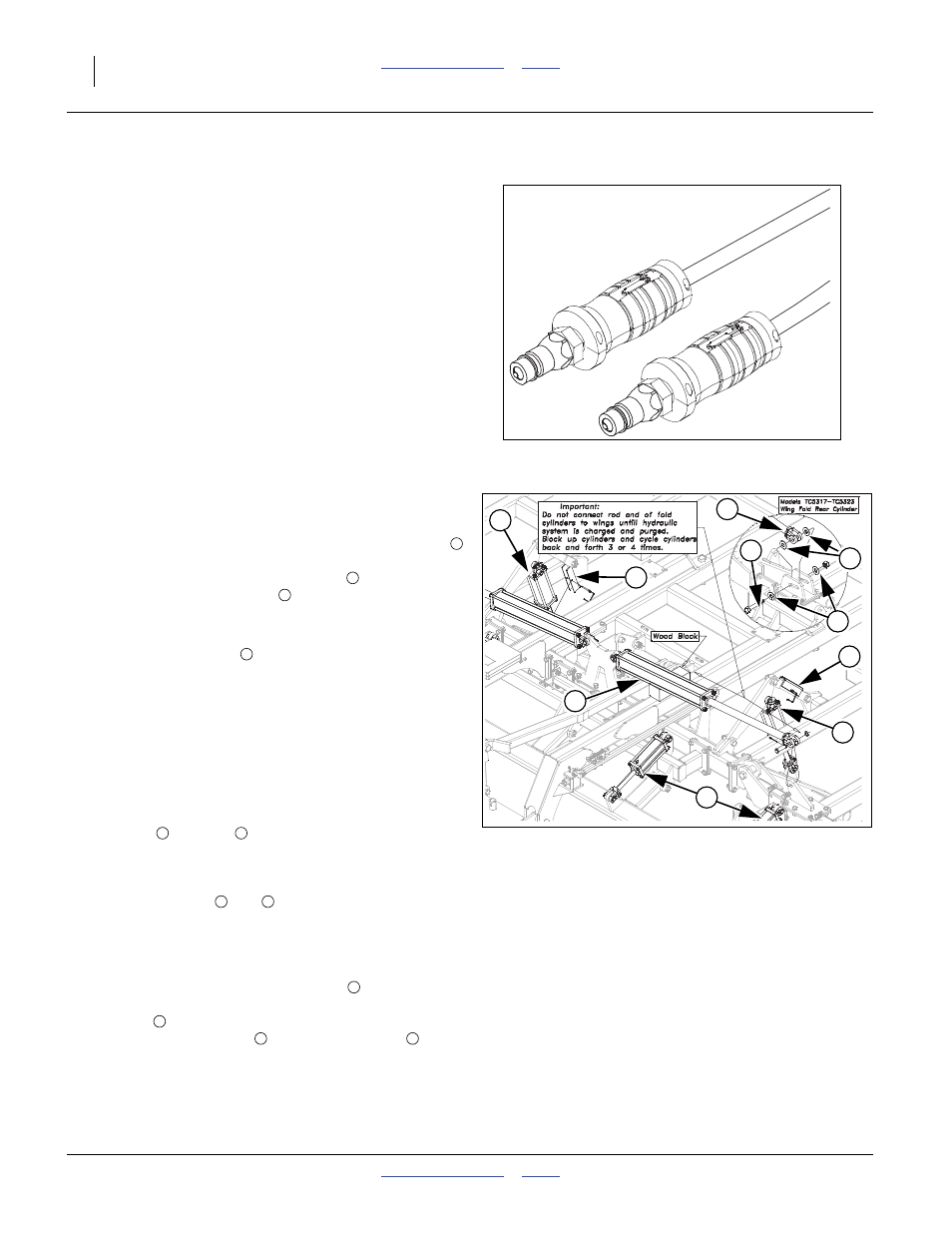
Purging Hydraulic System
Refer to Figure 27
121.Charge the lift system first. Extend the lift cylinders
(black handles) until the center section is fully raise.
Remove the cylinder transport locks
and install in
storage position on lift link
. Raise and lower the lift
system several times to purge air from system. Watch
for leaks and retighten fittings if necessary.
122.The gang lift system
(red handles), will need purged.
The wing gangs will not start to rise until the center cyl-
inders are fully extended and the master cylinders begin
to bypass oil through the rephasing ports, to the wing
cylinders. Continue to pump oil to the gang system until
the wing gang cylinders are also fully extended. At this
point, reverse the flow and raise the gangs, retracting all
cylinders. Repeat this procedure several times until all
the air is purged out of the system.
123.You may now charge the fold system. Before charging
the front
and rear
fold cylinders, make sure the rod
end of the cylinders are un-pinned or un-bolted and
block is under cylinder as shown, so that when the rod
is extended, it will clear the wing fold brackets. Extend
the fold cylinders
and
(green ends) completely and
then close them. Extend and retract the cylinders sev-
eral times to purge air from the system. Now the cylin-
ders may be extended far enough to be connected to
the wing fold brackets. Remove wood block and install
the 1 x 3 3/8 clevis pin (front cylinder
). 1.5 x 1.0 x.075
machine washer and 3/16 x 2 cotter pin. Hook up rear
cylinder
(Models 5317-5323 only) with the 1x 7 Gr. 8
special thread hex bolt
, four 1 flat washers
(two on
each side of rod end cylinder clevis and two on outside
fold bracket) and 1 nylock lock nut. Tighten bolt snug but
be sure cylinder clevis will still pivot.
Figure 26
Hose Handles
41552
Figure 27
Hydraulic Purging
42646
5
4
7
2
3
1
8
8
1
6
1
2
3
4
5
6
5
6
5
6
7
8