Valve, fitting and hose assembly, Depth stop, Install rebound valve and o-ring fittings – Great Plains TC5319 Assembly Manual User Manual
Page 24
20
TC5109-5323
Great Plains Manufacturing, Inc.
566-046E
04/12/2012
Valve, Fitting and Hose Assembly
Note: Refer to hydraulic layouts in Appendix for complete
hose routings
Refer to Figure 19
Depth Stop
100.Align holes in depth control valve
to top of depth stop
valve mounting bracket using 5/16 x 2 hex bolts
and 5/
16 lock washers.
101.Slide one end of (with 2 holes) depth stop tube
through slotted hole in depth stop valve mounting
bracket. Slide other end of depth stop tube
over lever
on torque tube, secure with 1/2 x 3 hex bolt
, 1/2 lock
washer and 1/2 nut.
102.Bolt depth stop screw assembly
to front of depth stop
tube
with 1/2 x 2 1/2 hex bolts
, 1/2 lock washers and
1/2 nuts.
103.Tighten all u-bolts to specs, See “Torque Values Chart”
Note: Install all hydraulic fittings as shown in steps below. See
hydraulic layouts in Appendix for proper hose routing.
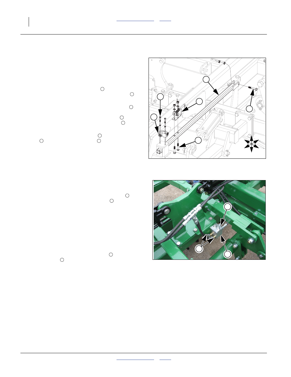
Install Rebound Valve and O-Ring Fittings
Refer to Figure 20
104.Thread straight (non- adjustable stud) fittings
into
ports V1, V2 and C2 of rebound valve
.
Note: Tighten as shown below. Do not over tighten as this
could cause damage to valves.
a.
Inspect all components for damage or contamination dur-
ing shipping.
b.
Lubricate o-ring and threads on fitting.
c.
Turn fitting into port until finger tight, See “Fittings
Torque Values” on page 28.
105.Thread elbow (adjustable stud) fitting
into port C1 of
rebound valve
.
a.
Follow steps a and b from the foregoing instructions, then
proceed with the following steps below.
b.Looking at fitting from end with nut/washer/o-ring
assembly, turn nut clockwise as far as possible.
a.
Using wrench, turn fitting into port until the washer
touches the port spot face. Continue turning fitting until
washer touches thread nearest wrench pad.
b.
Back off fitting counterclockwise not exceeding one revo-
lution until it is oriented in the correct position.
c.
Place wrench on the wrench pad of fitting to keep fittings
from turning, See “Fittings Torque Values” on page 28,
Figure 19
Depth Stop
42017
U
D
F
B
L
R
2
1
6
4
5
3
1
2
3
3
4
5
3
6
Figure 20
Rebound Valve Fittings
42621
2
1
3
3
1
2
1