5313-5315 wings – Great Plains TC5319 Assembly Manual User Manual
Page 19
Great Plains Manufacturing, Inc.
Assembly
15
04/12/2012
566-046E
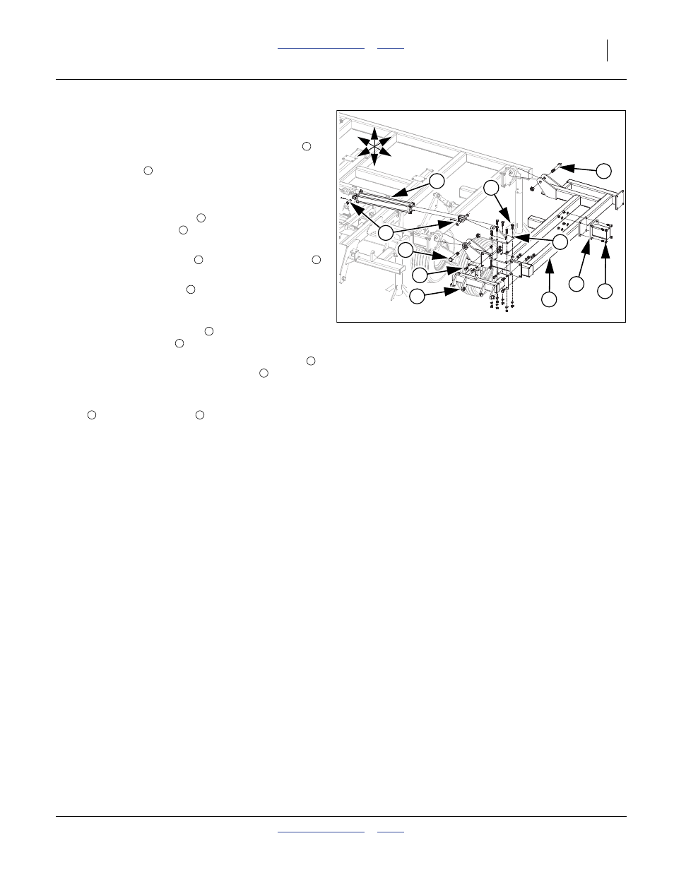
5313-5315 Wings
Refer to Figure 13
68. Carefully align holes in wing frame LH and RH
with
holes on center frame hinges. Secure with 1 1/4 x 8
Gr. 8 hex bolt
and 1 1/4 top lock nut.
Note: Tighten bolts snug but do not over-tighten as wings
need to pivot freely.
69. Attach wing gang mount
to front wing frame plates
with 3/4 x 2 hex bolts
, 3/4 lock washers and 3/4 hex
nuts.
70. Attach wing cylinder lug
with 3/4 x 2 hex bolts
, 3/
4 lock washers and 3/4 hex nuts.
Note: Wing shank mounts
are only used on some mod-
els, see machine and attachment layout drawings in
Appendix for proper placement.
71. Install wing shank mounts
to wing frame plate with
3/4 x 2 1/2 hex bolts
, 3/4 lock washers and 3/4 nuts.
72. Attach base end of the 4 x 30 x 2 fold cylinders
to
center fold bracket with 1 x 3 3/8 pins
, 1.5 x 1.0
x.075 machine washer and 3/16 x 2 cotter pin.
Note: Do not attach rod end of the 4 x 30 x 2 fold cylinders
to wing cylinder lug
until fold cylinders have
been purged of air, See “Purging Hydraulic Sys-
tem” on page 24.
73. Tighten all bolts to specs, See “Torque Values Chart”
Figure 13
5313-5315 Wings
42632
1
7
4
6
U
D
F
B
L
R
5
3
2
9
4
2
8
1
2
3
4
5
4
6
6
7
8
9
8
5