Turbo gang, Depth gauge, Turbo gang depth gauge – Great Plains TC5319 Assembly Manual User Manual
Page 23
Great Plains Manufacturing, Inc.
Assembly
19
04/12/2012
566-046E
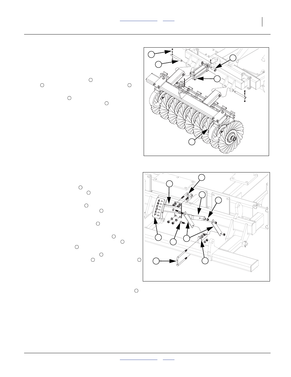
Turbo Gang
Note: See machine layouts in Appendix for proper gang
placement. The gang assemblies will come pre as-
sembled from factory and attached to the gang bar.
Refer to Figure 17
90. Install the gang assembly
using 1 x 9 1/2 hinge
pin
, secure with 3/8 x 2 1/4 Gr. 8 hex bolts
, 3/8
top lock nuts.
91. Attach cylinders
to ears on gang bars and gang
mounts, secure with 1 x 3 1/8 pins
, 1.5 x 1.0 x.075
machine washers and 3/16 x 2 cotter pins.
92. Tighten all bolts to specs, See “Torque Values
Depth Gauge
Refer to Figure 18
93. Install the link mount
to the center gang bar with
1/2 x 3 1/32 x 7 1/4 u-bolt
, 1/2 lock washers and 1/
2 nuts.
94. Install leveling weldment
to the center gang mount
with 1/2 x 5 1/32 x 4 1/2 u-bolts
, 1/2 lock washers
and 1/2 nuts.
95. Slide the depth gauge pointer
over the leveling
weldment bolt, secure with 1/2 lock nut.
96. Align one set of holes in the two links
, one on
each side of the depth gauge pointer hole
, secure
with 1/2 x 1 1/2 bolt
and 1/2 lock nut.
97. Attach the other end of the links
, one on each side
of the hole in the link mount
with 1/2 x 1 1/2 bolt
and 1/2 lock nut.
98. Tighten all u-bolts to specs, See “Torque Values
Chart” on page 27. Tighten the three lock nuts up
snug, but be sure the links will pivot.
99. Clean the surface where TC depth coulter decal
goes and peel backing off of decal and fasten decal
on plate. Firmly press decal to get all air bubbles out.
Figure 17
Turbo Gang
42013
1
4
2
5
3
1
2
3
4
5
Figure 18
Depth Gauge
42016
4
7
8
1
5
2
3
9
6
1
2
3
4
5
7
5
8
7
1
8
9