Place coupler, Mount a lh box assembly, Place coupler mount a lh box assembly – Great Plains 3S-5000HD Assembly Instructions User Manual
Page 28
24
3S-5000/F/HD/HDF SGS
Great Plains Manufacturing, Inc.
133-415M
2013-07-30
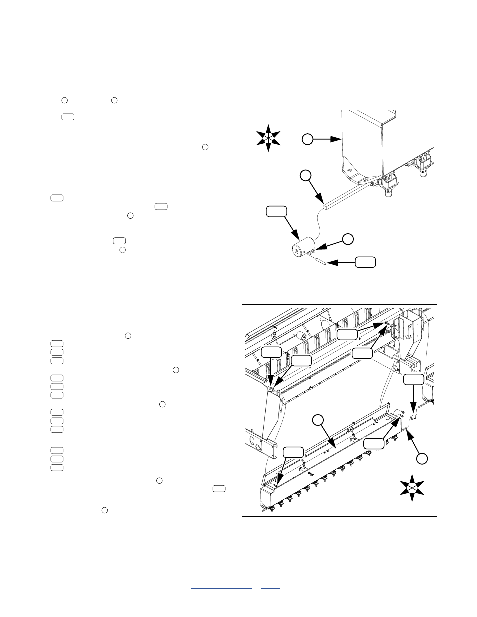
Place Coupler
The LH seed box meter shaft (not shown) is driven by the
RH box
meter shaft
. These two shafts are
connected inside the center mount weldment by a
coupler
.
The coupler is pinned to the LH shaft (not shown,
completed at step 105) after the LH box is installed. The
coupler is secured to the RH shaft by set screws
after
meter synchronization at step 108.
Start with the left wing.
Refer to Figure 36
99. Select one new:
133-120D 3S-5000 SML SDS DRIVE CPLG
Remove and save any roll pin
present.
Rotate the set screws
counter-clockwise until
their tips are clear of the square bore of the coupler.
Place the coupler
, set screw end first, onto the
RH box meter shaft
. Orient the coupler so that
the set screws are accessible to tools, from the
bottom or the top of the center mount weldment (not
shown). Do not tighten the set screws.
Repeat step 99 for the center section and right wing.
Mount a LH Box Assembly
100. For a Left Wing, Select one of the following small
seed box assemblies
, new:
133-393K 3S5000 SGS LW LH BOX ASY 6 IN
133-403K 3S5000 SGS LW LH BOX ASY 7.5IN
133-413K 3S5000 SGS LW LH BOX ASY 10 IN
For a Center Section, select one of
new:
133-388K 3S5000 SGS CT LH BOX ASY 6 IN
133-399K 3S5000 SGS CT LH BOX ASY 7.5IN
133-409K 3S5000 SGS CT LH BOX ASY 10 IN
For a Right Wing, select one of
new:
133-386K 3S5000 SGS RW LH BOX ASY 6 IN
133-395K 3S5000 SGS RW LH BOX ASY 7.5IN
133-405K 3S5000 SGS RW LH BOX ASY 10 IN
101. Select four sets of new:
802-388C HFS 3/8-16X1 GR5
804-013C WASHER LOCK SPRING 3/8 PLT
803-014C NUT HEX 3/8-16 PLT
102. Rotate the LH box meter shaft
so that the hole in
the shaft is aligned with the hole in the coupler
installed at step 99.
103. Mount the box
at the forward set of open holes in
the mounts and drives just installed.
Repeat step 96 through step 98 for the center and right
sections
U
D
L
R
B
F
120
2
238
3
Figure 36:
Place a Drive Coupler
34597
2
120
3
120
238
3
120
2
U
D
L
R
B
F
205
226
212
205
226
212
4
120
5
Figure 37:
Mount LH Small Seeds Assembly
34596
145
143
205
226
212
120