Weight bracket installation – Great Plains 3P1006NT Operator Manual User Manual
Page 95
Great Plains Manufacturing, Inc.
Appendix C - Accessory Installation
91
2011-12-20
151-144M
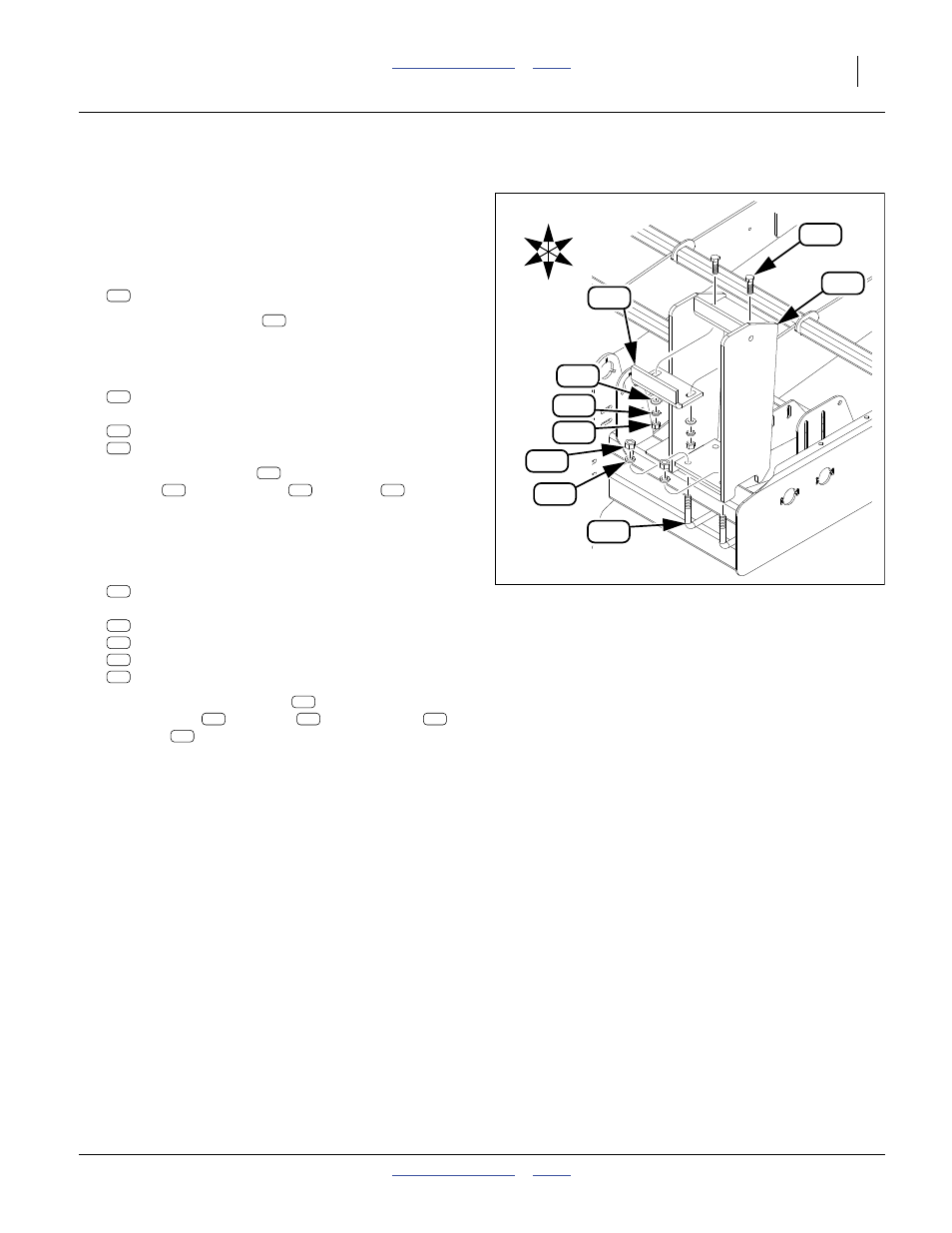
Weight Bracket Installation
These instructions apply to an installation of an optional
151-135A weight bracket kit.
Refer to Figure 66
Start at the left side of the drill.
1.
Select one:
151-134H WEIGHT BRACKET WELDMENT
2.
Position the weldment
at the left end of the top
front frame tool bar. Orient the beveled edges and
upper bracket to the back.
3.
Select two:
806-160C U-BOLT 3/4-10 X 4 1/32 X 4
and four sets:
804-023C WASHER LOCK SPRING 3/4 PLT
803-027C NUT HEX 3/4-10 PLT
4.
Secure the weldment
to the tool bar with the
U-Bolts
, lock washers
and nuts
.
5.
Examine the weights to be used, and determine how
to install the weight bracket adjustment legs. The
orientation depicted is not optimal for all weights.
6.
Select one:
151-271D WEIGHT BRACKET ADJ. LEG
and two sets:
802-055C HHCS 5/8-11X2 GR5
804-021C WASHER FLAT 5/8 SAE PLT
804-022C WASHER LOCK SPRING 5/8 PLT
803-021C NUT HEX 5/8-11 PLT
7.
Secure the adjustment leg
to the upper bracket
with the bolts
, washers
, lock washers
and nuts
. Depending on how your weights lock,
it may be necessary to leave the bolts loose until
after the weights are mounted.
8.
Repeat step 1 through step 6 for the right side of the
drill.
See “Drill Weight Adjustment” on page 34 for weight
selection.
Figure 66
Install Weight Bracket
28226
137
115
104
165
160
150
148
159
158
U
D
F
B
L
R
104
104
165
160
150
104
165
160
150
115
137
158
159
148
115
137
158
159
148