Caster brake adjustment, Caster brake adjustment (s/n a1059w+), Pressure plate adjustment – Great Plains 3P1006NT Operator Manual User Manual
Page 48
44
3P1006NT
Great Plains Manufacturing, Inc.
151-144M
2011-12-20
Caster Brake Adjustment
Caster Brake Adjustment (s/n A1059W+)
(applies to drills with serial numbers A1059W+
For serial number A1058W-, see page 45)
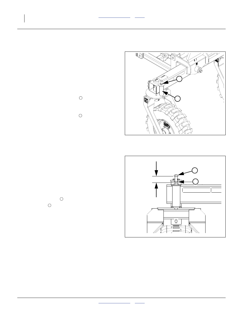
Refer to Figure 33
The rear lift-assist wheels each have independent
adjusters for the caster pivot. The adjustments will vary
depending on different field-to-field conditions as well as
road transport conditions.
If the caster is oscillating during transport turns or in field
use, adjust the pressure plate bolt
.
Refer to Figure 34
The factory setting for both adjustments is
1
3
⁄
4
in. (4.4 cm) from the face of the bolt head to the top
of the weldment, this measurement is a starting point
and will need to be fine tuned from field-to-field as
conditions vary. Depending on conditions, adjustment
may be needed to go from field to road transport. If
caster brake components are ever replaced, return the
bolts to the factory setting.
Pressure Plate Adjustment
1.
Loosen the jam nut
.
2.
Turn the bolt
clockwise until the spring is fully
compressed.
3.
Back the bolt out
1
⁄
4
in. (6 mm).
4.
Tighten the jam nut.
Caster Pressure Plate and Tube:
The tube acts as a pivot brake
, and helps prevent
caster oscillation during transport.
Figure 33
Rear Caster Adjustments
(s/n A1059W+)
32058
1
2
1
2
Figure 34
Rear Caster Adjustment Bolts
(left side shown)
32059
1
3
⁄
4
in.
4.4 cm
2
3
3
2