Hydraulic setup, Hydraulic charge and bleed – Great Plains 3P1006NT Operator Manual User Manual
Page 90
86
3P1006NT
Great Plains Manufacturing, Inc.
151-144M
2011-12-20
Hydraulic Setup
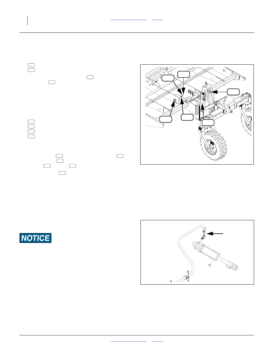
Refer to Figure 60
28. Select one each:
811-065C EL 9/16MJIC 9/16MORB
841-286C HH1/4R2 134 9/16FJIC 1/2MNPT
29. Secure the FJIC end of hose
to the end port of
the elbow
. Tighten to specification.
30. At the MORB fitting, fully back off the jam nut.
Loosely connect the MORB end of hose to the top
(base end) port of the cylinder. Orient the elbow so
that the hose route is down. Do not tighten ORB
fitting or its jam nut.
31. Select two sets:
800-239C 1.125 WIRING AND TUBE CLIP
802-017C HHCS 3/8-16X1 GR5
804-013C WASHER LOCK SPRING 3/8 PLT
803-014C NUT HEX 3/8-16 PLT
Note: The hose is secured to the frame brace plate at two
points.
32. Place the clip
around the feed-line hose
.
Insert the bolt
. Loosely secure with lock
washer
and nut
. Tighten the nut.
33. Feed-line hose
terminates in a
1
⁄
2
in. male NPT
fitting. Adapt this to the style and size of coupler
required to connect the drill to a hydraulic source for
the next step. The drill does not include a coupler for
this purpose. If fitting the coupler for the tractor to be
used with this drill in the field, apply liquid sealant to
the threads before making the connection. Do not
use plastic tape sealant.
Hydraulic Charge and Bleed
Refer to Figure 61
Bleed pressurized lines only at:
JIC (Joint Industry Conference, 37
° flare) or
NPT (National Pipe Thread, tapered thread) fittings.
Avoid bleeding at:
ORB (O-Ring Boss)
Never bleed pressurized lines at:
QD (Quick Disconnect) fittings.
See “Bleeding Hydraulics” on page 52.
Figure 60
Install Hydraulic Lines
32069
147
156
169
183
134
130
169
183
183
169
130
134
156
147
130
183
134
156
147
183
Figure 61
Lift-Assist Cylinder Bleed
32056