Caster shaft installation, Begin install shaft, Install lock out plunger – Great Plains 3P1006NT Operator Manual User Manual
Page 87: Finish install shaft, Install lock tube, Install caster zerks
Great Plains Manufacturing, Inc.
Appendix B - Pre-Delivery
83
2011-12-20
151-144M
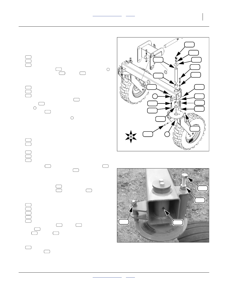
Caster Shaft Installation
Refer to Figure 55 and Figure 56
Begin Install Shaft
11. Select one each:
161-116D LIFT ASSIST CASTER SHAFT
802-060C HHCS 5/8-11X4 GR5
803-024C NUT LOCK 5/8-11 PLT
Insert caster shaft
through caster frame plate
and secure with bolt
and nut
.
Install Lock Out Plunger
12. Select one each:
807-175C SPRING COMP .796ODX.065WX1.
151-355D 1007 LOCK OUT PLUNGER
805-076C PIN ROLL 3/16 X 1 3/4 PLT.
Place lock out plunger spring
over lock out
plunger
. Inserting from the bottom up of plunger
tube
, force both into the plunger tube and secure
with roll pin
.
Note: The lock out plunger tube
MUST be facing to the
front of the drill. If it is facing to the rear, the pivot
arm tube is on backwards and must be switched.
Finish Install Shaft
13. Select one each:
161-056D CASTER SPACER
161-114D CASTER RETAINER CAP
and two each:
890-072C BUSHING 2 1/2 X 2 1/4 X 2 LG.
802-034C HHCS 1/2-13X1 1/4 GR5
804-015C WASHER LOCK SPRING 1/2 PLT
Place spacer
over the top of the caster shaft
.
With mallet, drive one bushing
into shaft hole on
bottom of pivot arm tube and one in top of hole on
pivot arm tube. Place shaft up through these bushings
in pivot arm. Complete assembling shaft by placing
caster retaining cap
on top and securing with two
washer lock springs
and two bolts
.
Install Lock Tube
14. Select one each:
266-020D UHMW RND 2.0 DIA X 2.0 LONG
807-143C SPRING COMP 1.88OD X .36 +
266-012D PLATE RND 3/16" THK 1 7/8"
802-067C HHCS 3/4-10X4 GR5 FTHD
803-048C NUT HEX JAM 3/4-10 PLT
Assemble bushing
, spring
and small round
plate
. Push up inside lock tube. Complete with
nut
and bolt
.
Install Caster Zerks
15. Select one:
800-001C GREASE ZERK STRAIGHT 1/4-28
Install zerk
in shaft at end of pivot arm tube.
16. Repeat all steps for other caster.
Figure 55
Caster Shaft Installation
32115
149
1
139
119
124
116
116
167
164
2
123
128
152
141
184
121
120
157
135
U
D
B
F
R
L
121
139
149
121
139
149
167
116
164
167
116
164
119
120
184
135
157
Figure 56
Caster Assembled
32119
164
128
152
141
119
121
184
120
157
135
124
166
123
141
152
124
124
123
152
141
128
128