Spreader and scraper, Disk, Gauge wheels – Great Plains PT8030 V1012 Operator Manual User Manual
Page 49: Caution
47
Section 7 Maintenance and Lubrication
PT6030 and PT8030 Pull-Type Planter 401-032M
10/10/12
Great Plains Mfg., Inc.
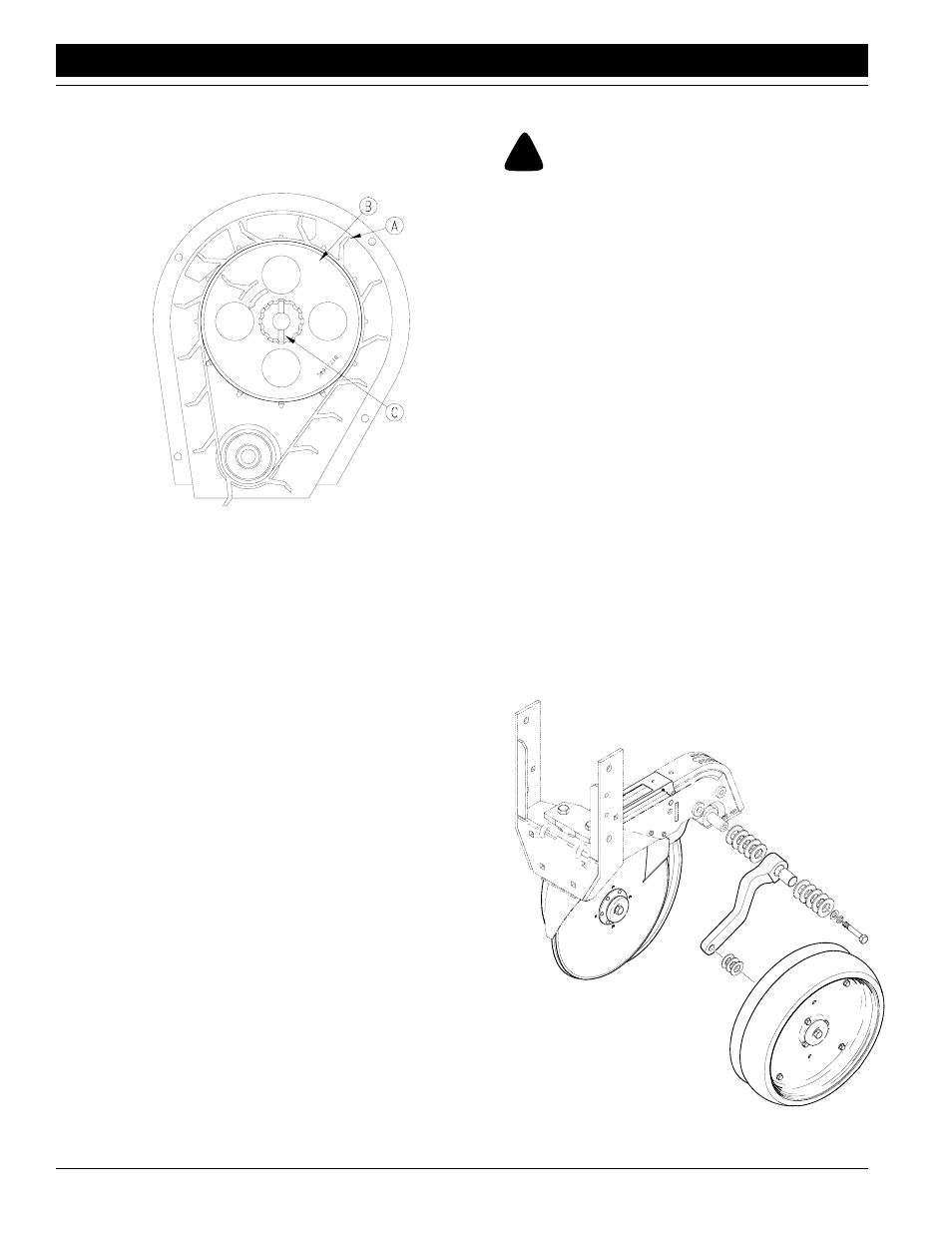
IMPORTANT: See Figure 7-6 if belt is replaced. Be certain
paddles (A) are oriented as shown. Belt drive wheel (B)
may be removed by removing spring pins (C).
Finger Meter Belt Orientation
Figure 7-6
15049
3.
Reassemble in the reverse order.
Spreader and Scraper
The spreader and scraper between the disks will periodi-
cally need replacing. These components scrape dirt off
the disks and protect the seed tube.
To inspect or replace the spreader or scraper do as fol-
lows:
1.
Remove the side gauge wheel and the arm from the
row unit.
2.
Remove the disk blade. Be careful, disks wear very
sharp!
3.
Remove both of the 1/4" bolts holding the scraper and
spreader.
4.
If the sides of the seed tube are worn, replace the
scraper and spreader.
5.
Install the scraper and spreader with 1/4" bolts.
Torque the bolts to the correct values as listed in the
Torque Values Chart in “Section 10 Appendix” on
page
62.
6.
Install the disk and torque the bolt to the correct value
as listed in Torque Values Chart in “Section 10 Ap-
pendix” on page
7.
Install the gauge wheel according to directions under
the Gauge Wheels heading below.
Disk
!
CAUTION!
Disk blades wear very sharp. Handle with care.
As the disks on the row unit wear, removal of shims may
be required to maintain contact point. To remove disk do
as follows:
1.
Remove side gauge wheels and arm from the row
unit.
2.
Remove 3/4" bolts retaining the disks.
3.
Measure disk diameter, if disk measures 14 1/2" or
less replace disk.
4.
If contact is to be increase, move shims from behind
disk to outside disks. This will increase the contact be-
tween the disks.
5.
Install disks and tighten 3/4" bolts to torque values in
Specification Section.
6.
Install gauge wheels and arms according to directions
in this section.
Gauge Wheels
Periodically check gauge tires to be sure there is contact
or a 1/16" gap between the tires and disks.
For installation or adjustments proceed as follows:
1.
Remove the 1/2" bolt holding arm on to the shank.
2.
If tire needs to be closer to disk, move an appropriate
amount of shims from inside of arm to outside, see
Figure 7-7. Each shim is 0.050 thick.
Gauge Arm, Spindle, and Shims
Figure 7-7
12354