Closing wheel alignment, Closing wheel offset, Closing disk adjustments – Great Plains PT8030 V1012 Operator Manual User Manual
Page 28: Closing disk tube shield
26
Section 4 Adjustments
10/10/12
PT6030 and PT8030 Pull-Type Planter 401-032M
Great Plains Mfg., Inc.
Closing Wheel Alignment
Refer to Figure 4-9:
If one closing wheel is running in the seed trench or the
wheels are not centered over the seed trench, adjust the
closing wheels as follows:
1.
Raise the planter slightly to remove weight from the
closing wheels.
2.
Loosen the two 1/2" bolts.
3.
Turn the press wheel adjuster left or right to center the
wheels over the seed trench.
Tighten the 1/2" bolts to the correct torque values in the
Torque Value Chart in “Section 10 Appendix” on
page
62.
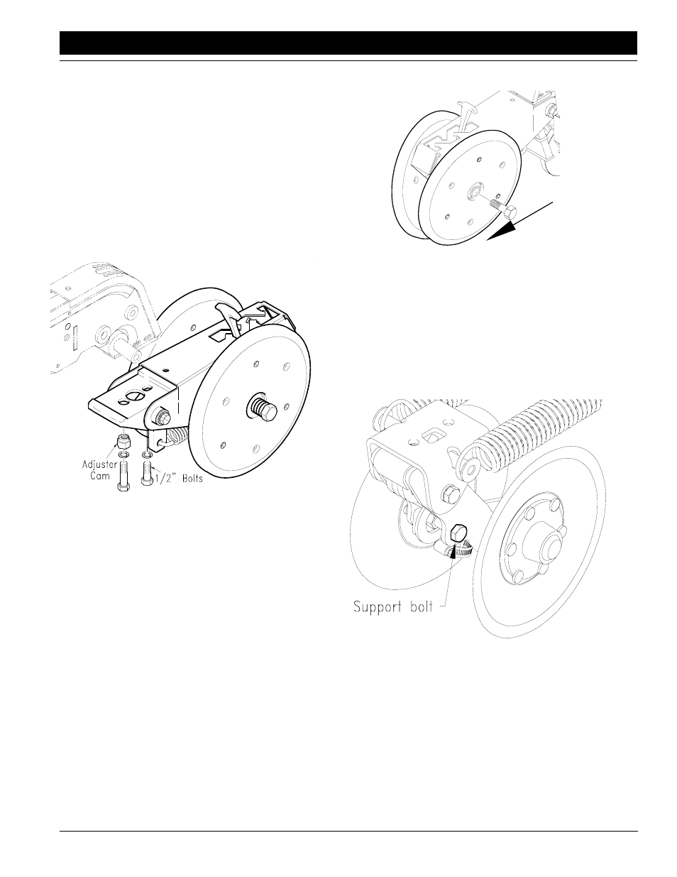
Closing Wheel Alignment
Figure 4-9
12418
Closing Wheel Offset
The 1x12 wheels can be offset to help prevent trash from
plugging the closing wheels. If the closing wheels are not
offset, the wheels should be located in the front holes of
the press wheel arm.
To offset the wheels, do as follows:
1.
Raise planter slightly to remove weight on the closing
wheels.
2.
Remove the 3/4” bolt holding the wheel, see
Figure 4-10.
3.
Move the wheel to the rear hole and attach with the 3/
4" bolt. Tighten the bolt to the correct torque value list-
ed in the Torque Value Chart in “Section 10 Appen-
dix” on page
62.
Closing Wheel & Offset
Figure 4-10
12347
Closing Disk Adjustments
The closing disk options consists of two disks and a
6 1/2 x 12 press wheel. The disk down pressure can be ad-
justed to provide closing of the seed trench.
To adjust the down pressure, ratchet the spring cam to the
next cam height by turning the head of the support bolt
clockwise. Refer to Figure 4-11.
Closing Disk & Tube Holes
Figure 4-11
14913
Closing Disk Tube Shield
To prevent clogging in insecticide hoses:
1.
Clamp closing disk tube shield to closing disk.
2.
Insert insecticide hose (#1) inside the closing disk
tube shield (#2) as shown in Figure 4-12. When unit is
picked up the insecticide hose should be about 1/4”
above the bottom of the shield.