Center tower installation, Wing tower installation, Center tower installation wing tower installation – Great Plains CTA4000 Predelivery Manual User Manual
Page 26: Rota te t ow ard center of drill
22
CTA4000 & CTA4000HD
Great Plains Manufacturing, Inc.
160-037Q
2013-08-21
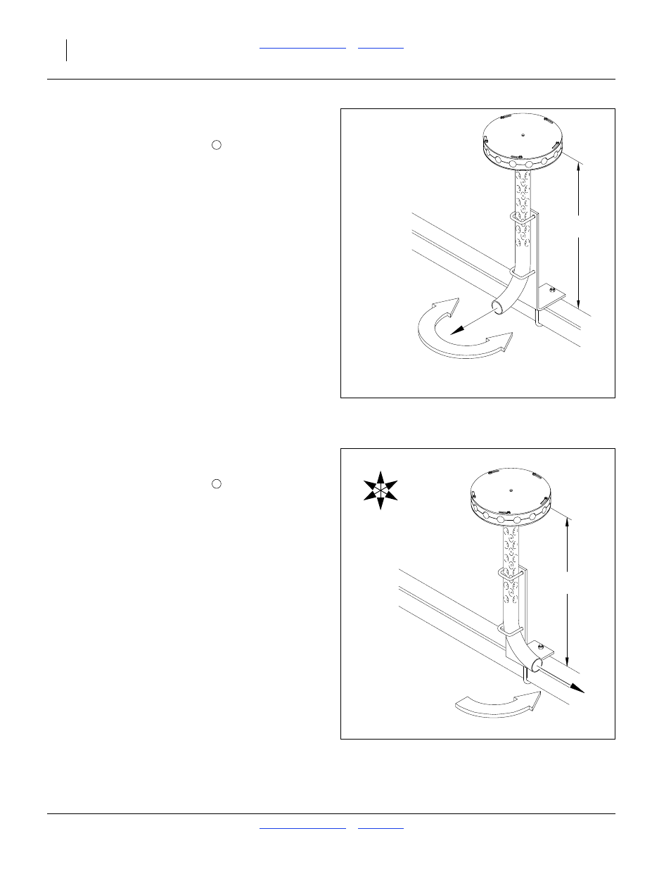
Center Tower Installation
Refer to Figure 27 and Figure 27
2.
Loosen 2
1
⁄
2
×2
1
⁄
2
inch U-bolts
that hold tower on
support bracket.
3.
Reposition tower so bottom of lower round plate is
about 20
3
⁄
4
inches (52.7 cm) above implement
frame. Turn inlet tube toward center of implement.
Wing Tower Installation
Refer to Figure 28 and Figure 28 on page 22
4.
Loosen 2
1
⁄
2
×2
1
⁄
2
inch U-bolts
that hold tower on
support bracket.
5.
Reposition tower so bottom of lower round plate is
about 25 inches (63.5 cm) above implement frame.
Turn inlet tube along the rear frame tube and toward
center of implement.
6.
After towers have been installed and before any
seed hoses are installed, slowly fold implement while
watching to be sure there is no interference.
Refer to CTA4000 or CTA4000HD Operator’s Manual
for fold and unfold instructions.
7.
If a tower interferes with any part of implement,
completely reposition tower. Repeat these steps until
implement can be folded without tower interference.
Figure 27
Position Center Tower
16198
ROTA
TE T
OW
ARD
CENTER OF DRILL
20¾in (52.7cm)
P
Figure 28
Position Wing Tower (Left Shown)
29338
25in (63.5cm)
25in (63.5cm)
ROTA
TE ALONG REAR
ROTA
TE ALONG REAR
FRAME TUBE T
OW
ARD
FRAME
TUBE
TOW
ARD
DRILL CENTER
DRILL CENTER
U
D
B
F
R
L
P