Upper housing lubrication, Discharge spout, Truss – Wheatheart GHR 80/100 x 31-71ft Augers EMD User Manual
Page 24
3. A
SSEMBLY
W
HEATHEART
- G
RAIN
A
UGER
EMD
3.7. U
PPER
H
OUSING
L
UBRICATION
GHR 80
X
31’-71’ & 100
X
31’-71’
24
30642 R0
3.7. UPPER HOUSING LUBRICATION
Fill enclosed upper drive housing with grease.
For continuous use in extreme cold conditions, semi-fluid arctic grease or heavy
oil may be used.
3.8. DISCHARGE SPOUT
Attach discharge spout with half tube clamps and 7/16” x 1-3/4” bolts and
locknuts as required.
¨
Some augers are equipped with weld-on discharge spouts.
If a safety spout is being used with this auger, the safety release door should be
on the left side of the auger, as determined when standing at intake facing the
discharge end.
3.9. TRUSS
See Figure 3.12, 3.13, 3.14, and 3.15.
1. Fasten lower truss anchor to bracket.
• use two 7/16” x 1" bolts and locknuts.
2. Fasten the center truss support bracket on 46’ and 51’ augers with two
7/16” x 1" bolts and locknuts (Figure 3.13).
¨
• The 56’ and 61’ augers require 2 center truss support brackets, each fas-
tened with two 7/16” x 1" bolts and locknuts.
¨
• The 71’ auger requires a high truss support center bracket located
between the 2 standard support brackets. Fasten with two 7/16” x 1" bolts
and locknuts (Figure 3.14).
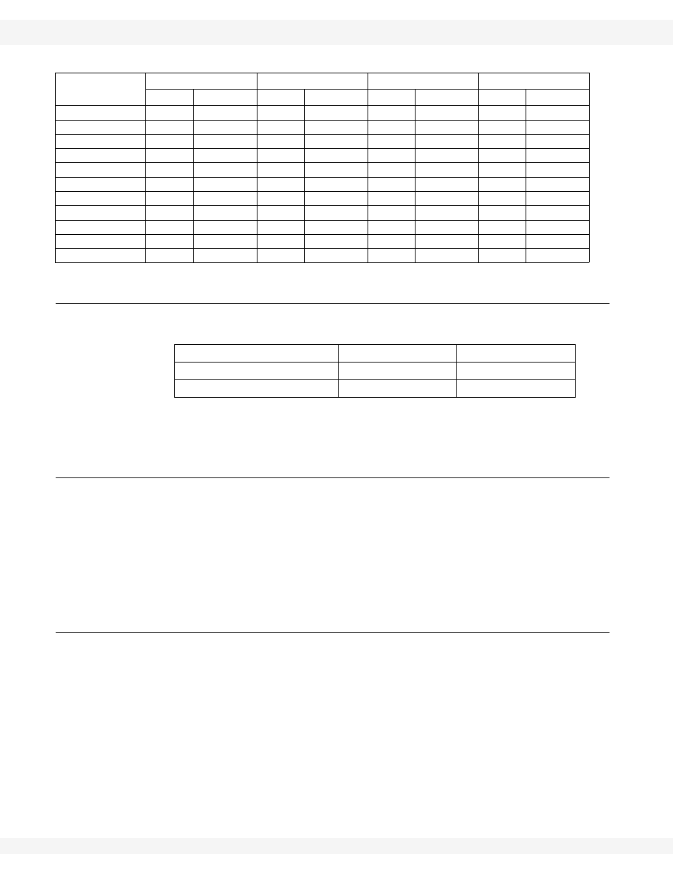
Table 3.3 Driveshaft Shielding Sequence
Auger Size/
Length
Step 1
Step 2
Step 3
Step 4
Qty
Length
Qty
Length
Qty
Length
Qty
Length
8” x 31’
1
24”
1
42”
3
48”
1
42"
10" x 31’
1
42”
5
48”
1
42”
--
--
8” x 36’
1
48”
1
42”
4
48”
1
42"
8” x 41’
2
48”
1
42”
4
48”
1
42"
10" x 41’
1
24”
2
42”
5
48”
1
42"
8" x 46’
3
42”
4
60”
1
48”
--
--
8” x 51’
1
48”
6
60”
1
48”
--
--
10" x 51’
1
24”
8
48”
1
42”
--
--
8" x 56’
10
48”
1
42”
--
--
--
--
8"/10” x 61’
1
24”
10
48”
1
42”
--
--
8"/10” x 71’
1
42”
12
48”
1
42”
--
--
GHR80 x 31' - 51'
750 g
26 oz
GHR80 x 56' - 71'
900 g
32 oz
GHR100 x 31’ - 71’
1100 g
40 oz