Driveshaft shield, Caution – Wheatheart GHR 80/100 x 31-71ft Augers EMD User Manual
Page 22
3. A
SSEMBLY
W
HEATHEART
- G
RAIN
A
UGER
EMD
3.6. D
RIVESHAFT
S
HIELD
GHR 80
X
31’-71’ & 100
X
31’-71’
22
30642 R0
5. Place gearbox assembly with mounting plate onto the mounting bracket
welded to lower tube and secure with four 7/16” x 1" bolts and locknuts.
Note:
Maintain a minimum 1/16” clearance between chain coupler sprockets.
¨
Gearbox mounting procedure for the following augers (Figure 3.9):
• 8" x 56’-61’-71'
• All 10" augers
6. These augers are equipped with chain couplers. Remove chain and secure
half the chain coupler to the driveshaft. Use a Woodruff key on 8" augers and
a 1/4” x 1-1/2” square key on 10" augers.
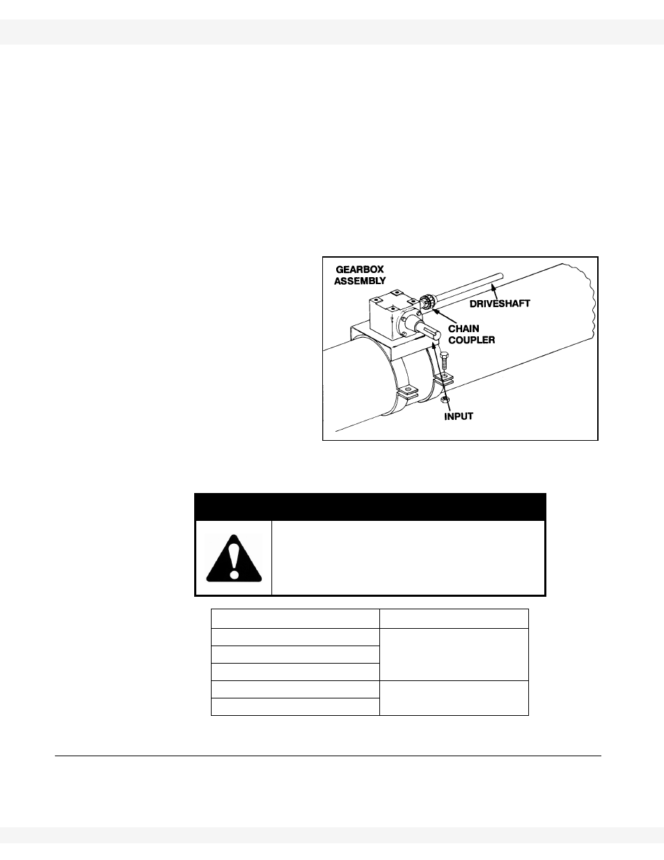
7. Place gearbox assembly on auger tube. Reinstall chain leaving a 1/16”
clearance between chain coupler sprockets.
8. Secure
gearbox
assembly to auger tube
with half tube clamps and
four 7/16” x 1" bolts and
locknuts.
9. After mounting gearbox
assembly, adjust sprocket
clearance to approxi-
mately 1/16”. Tighten set
screw.
Add EP90 lube oil to the
gearbox before operating
auger. Failure to do so will
void warranty. Do not overfill.
Fill half full only.
3.6. DRIVESHAFT SHIELD
1. First, install the chain coupler guard, then install the driveshaft shields,
working from gearbox assembly to discharge end. Refer to Table 3.3 for the
proper sequence.
CAUTION
Ensure that gearbox assembly is mounted in
the proper location (Figure 3.6).
Failure to properly locate gearbox will result in
an unsafe operating condition.
Auger
Oil Requirements
all 6”
224 ml
(8 fl oz)
all 7”
8” (up to and incl. the 51’)
8” (56’ and up)
700 ml (25 fl oz)
all 10”
Figure 3.9
Important: