Intake hitch, Driveshaft, Procedure 1 - driveshaft addition – Wheatheart GHR 80/100 x 31-71ft Augers EMD User Manual
Page 18: Intake hitch 3.4. driveshaft, 1 - d
3. A
SSEMBLY
W
HEATHEART
- G
RAIN
A
UGER
EMD
3.3. I
NTAKE
H
ITCH
GHR 80
X
31’-71’ & 100
X
31’-71’
18
30642 R0
4. Slide track shoe along full length of track to make certain there is no binding
and that track ends are properly aligned. The upper and lower tracks must be
aligned to allow track shoe to roll smoothly over this joint (Figure 3.3).
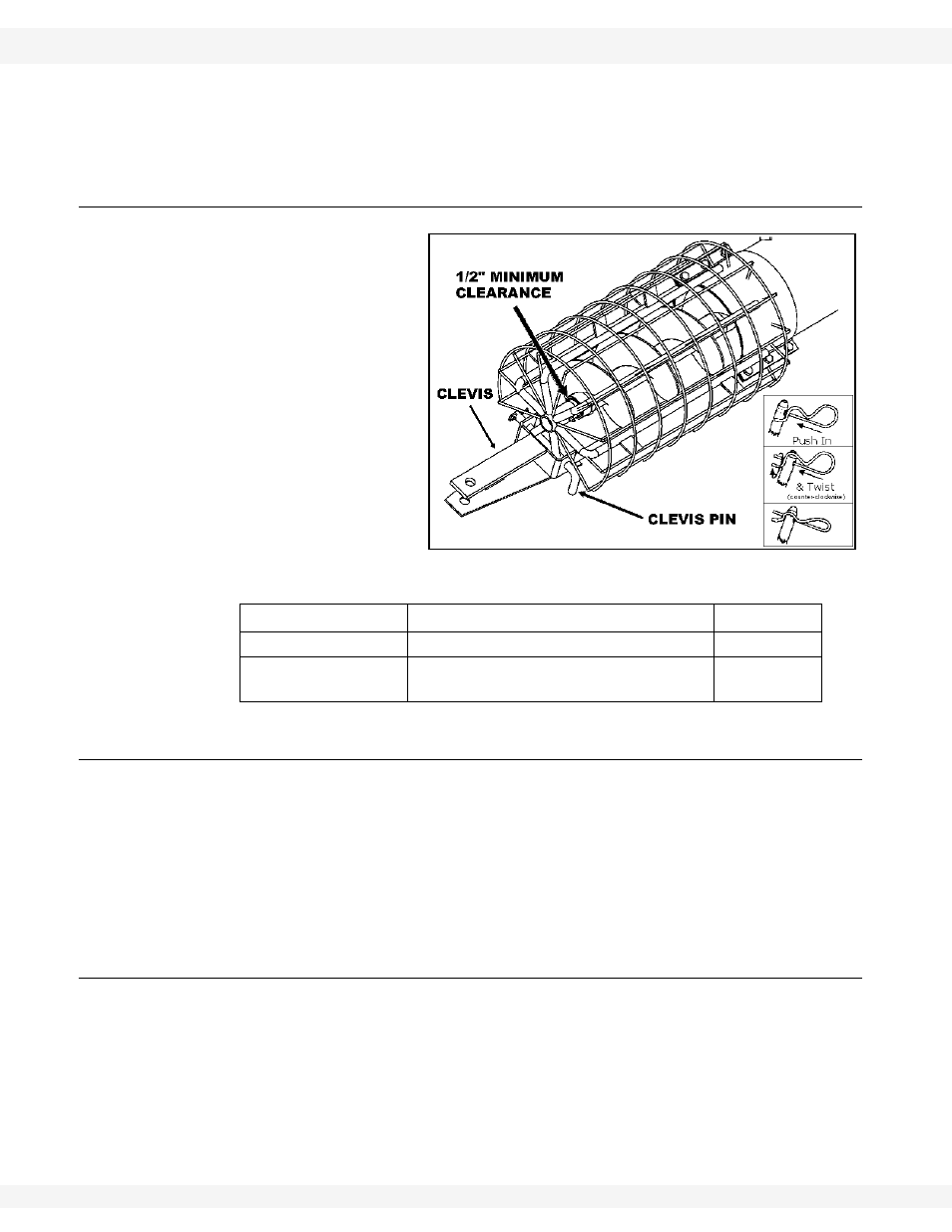
3.3. INTAKE HITCH
1. Clean dirt and paint
from lower flight stub
and intake bushing.
2. Attach intake hitch to
lower auger tube and
tighten securely.
3. Maintain
1/2”
clearance between
bushing and end of
flight.
4. Attach clevis to intake
hitch with clevis pin
and gripclip.
3.4. DRIVESHAFT
The installation procedure for the driveshaft and gearbox assembly on the EMD
auger depends on the size and length of the auger.
Because most of the driveshaft is pre-installed, consult Figure 3.6 before
proceeding with the assembly of your auger.
Since the length of the driveshaft determines the location of the gearbox, it is
very important that the length is correct for the corresponding auger.
3.4.1. P
ROCEDURE
1 - D
RIVESHAFT
A
DDITION
¨
For all 8” augers up to and including 51’, and the 8" x 71’ augers. (For other
sizes, see Procedure 2 on the next page.)
For augers requiring additional driveshaft segment(s), proceed as follows (listed
above or on Figure 3.6):
1. Clean dirt and/or paint from driveshaft ends and from inside shaft
connector(s).
2. Slide shaft connector halfway onto the last pre-installed driveshaft segment.
Part
Size
Amt.
Intake Hitch
7/16” x 1” bolt and locknut
6
Clevis Pin
5/8” for the 8” auger
3/4” for the 10” auger
1
Figure 3.5