Connecting the unit, Connecting power – ClearOne XAP TH1 User Manual
Page 12
TECHNICAL SUPPORT: 1.800.283.5936 (USA) OR 1.801.974.3760
8
INSTALL ATION & OPERATION
• INSTALL ATION
Connecting the Unit
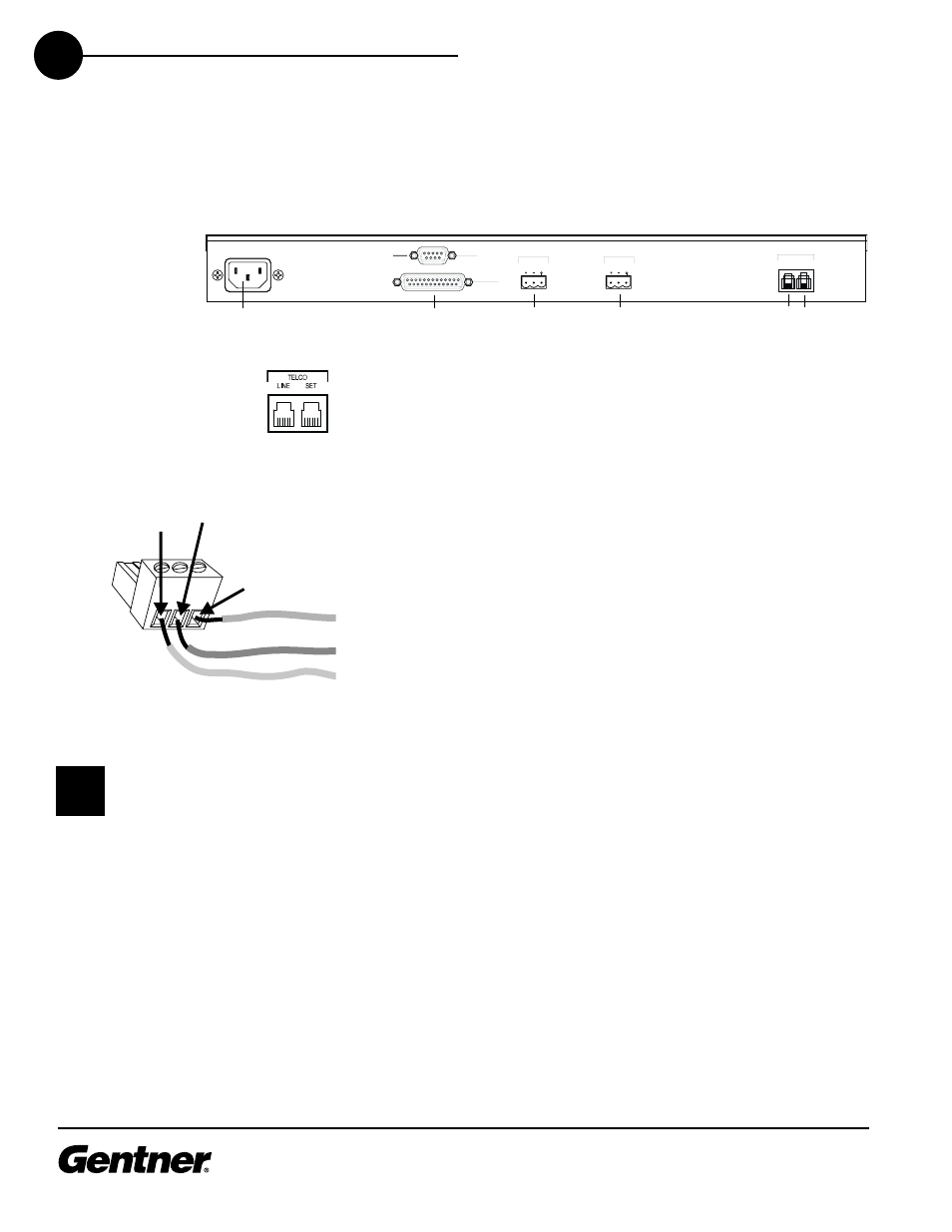
Refer to XAP TH1 back-panel connections (See Figure 5, below) for a
description and placement of each of the connections you will be
making. Each connector is numbered for easy identification. To install
your XAP TH1, follow these step-by-step instructions:
1.
Plug your telephone line from the wall jack into the RJ-11C Line jack
[6].
2. Plug your telephone set into the RJ-11C Set jack [7].
3. If you are using a remote control device (Crestron, Panja AMX, etc.),
connect via the RS-232 port [2]. You can also connect to a PC using
this port.
4. If you are using a remote control for parallel control and hybrid
status, plug it into the DB25 Remote connector [3].
5. Wire the XAP TH1 to the XAP 800 using the provided three-terminal
Phoenix push-on connectors. These connectors are designed for
easy wiring; simply insert the desired wire into the appropriate
connector opening and tighten down the top screw.
Transmit Input Audio connected to the Transmit Input [4] will
be sent down the telephone line.
Receive Output Audio from the Receive Output [5] (telephone
participant audio) is passed to the XAP 800 for further routing
and distribution. See Figure 4 on page 7.
Connecting Power
The power input [1] will operate at any level between 100–240VAC,
50–60Hz, 15W (typical). Plug in the XAP TH1 to complete the hardware
installation.
1
2
3
4
5
6 7
VOLTAGE RANGE 100V - 240V 2A
FREQUENCY 50Hz / 60Hz
REMOTE
RS-232
TRANSMIT
INPUT
RECEIVE
OUTPUT
TELCO
LINE SET
Figure 6. RJ-11C telephone-line connector
Figure 7. Phoenix push-on connector
Figure 5. XAP TH1 back-panel connectors
+
–
Ground
Negative
Positive
The three terminals in the
Phoenix connector corre-
spond with the back-panel
audio contacts (from left to right):
+(positive), –(negative), and
(ground).
✍