8200 only - how to change hand of lock, 7900 - see instruction label on lockbody), A7896b – SARGENT 7900 Mortise Lock User Manual
Page 4
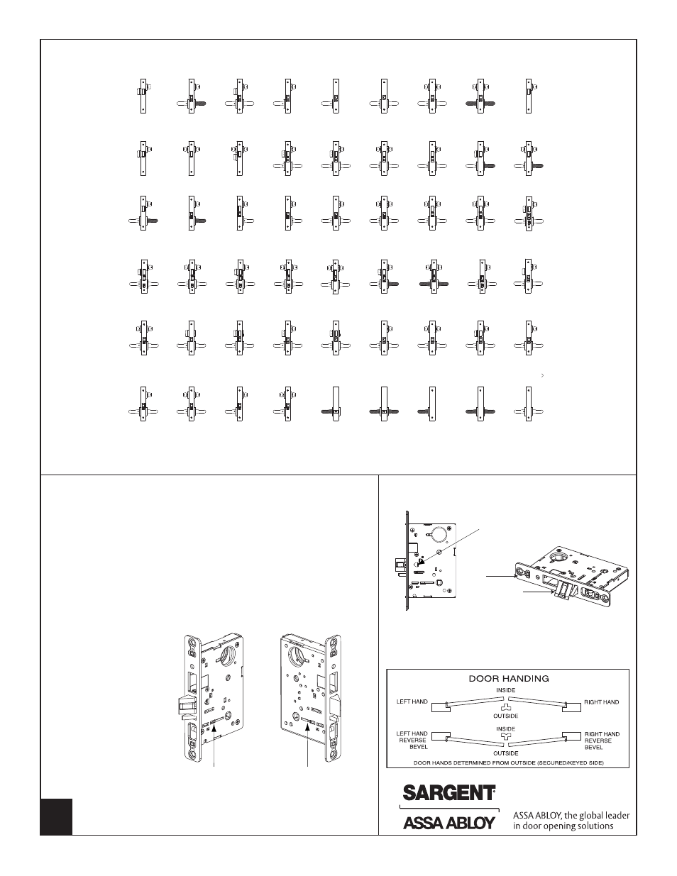
8200 Only - How To Change Hand of Lock
(7900 - see instruction label on lockbody)
03/F29
Classroom
dead lock
21/F17
Dead lock
30
Dummy trim
dead lock
56
Inner entry lock
89/F06
Hold back lock
90
Classroom
security hold back
lock
91
All purpose hold
back lock
92
All purpose hold
back lock
I
93
Dummy trim
94
Dummy trim
95
Single trim
dummy lock
96
Double trim
dummy lock
97
Active trim
dummy lock
65/F22
Privacy bedroom
or bath lock
66/F19
Privacy bedroom
or bath lock
67/F26
Institutional
privacy lock
68/F02
Privacy bedroom
or bath lock
70/71
Electrical
70: Fail safe
71: Fail secure
72/73
Electrical
72: Fail safe
73: Fail secure
76/77*
Electrical
entry lock
(* No cylinder on
77 function
78/79*
Electrical
entry lock
(* No cylinder on
79 function
45/F12
Dormitory or
exit lock
46/F11
Dormitory or
exit lock
47/F08/F10
Front door lock
or apartment
corridor lock
48/F35
Store door lock
49
Security deadbolt
50/51F15
Hotel guest
lock/Store room
deadbolt lock
52
Institution
deadbolt lock
55/F04
Office or
entry lock
31
Utility
lock
35
Storeroom
lock
36
Closet
lock
37/F05
Classroom
lock
38/F32
Classroom
security intruder
latchbolt lock
39/F33
Classroom
security intruder
deadbolt lock
40/41/F34
Classroom
security intruder
deadbolt lock
22/F16
Dead lock
23
Classroom
dead lock
24/F21
Room door
lock
25/F13
Dormitory or
exit lock
26/F14
Store door lock
27
Closet or
storeroom lock
28
Dummy trim
dead lock
29
Dummy trim
dead lock
04/F07
Storeroom
closet lock
05/F04
Office or
entry lock
06
Storeroom or
service lock
13/F31
Communicating
or exit lock
15/F01
Passage or closet
latch
16/F09
Apartment or exit
or public toilet
lock
17/F30
Asylum or
institutional lock
20/F18
Dead lock
43/F20
Apartment
corridor door lock
59
Double locking
SARGENT 8200 Series Mortise Lock Function List (7900 functions see catalog)
Note: Beveled surface of latch must face strike. The
deadlatch is self adjusting. To change hand of latch:
Note: Red surface of locking piece must face secure
(keyed/locked) side of door.
To rotate locking piece:
1. Position lockbody with red surface of locking piece visible
2. Insert blade type screwdriver into locking piece slot to rotate
locking piece
3. Push locking piece toward back of lock body and rotate 180°
until RED surface shows on opposite side
IMPORTANT: 04, 06, 13, 17 and 31 Functions require:
a. Green catch screw to
be removed
b. Rotate hub 45 degrees
to vertical position
c. Rotate locking piece
for required hand
d. Red surface faces
locked side of door
e. Rotate hub to the
original 45 degree
position as shown
on lockcase
f. Green catch screw
is then reinstalled
Red color indicates locked
side of door or hold back
side (91 and 92 Functions)
Locking
piece slot
Lock front
Latch
1. Insert flat blade screwdriver
into the spade shaped slot
2. Rotate screwdriver 90º to push latch out until back
of latch clears lock front. Then rotate latch 180º.
Latch will then re-enter lockbody.
(Note: Latch can not be unscrewed)
NOTE: 05 FUNCTION HAS A THUMB TURN ON THE INSIDE FACE
OF DOOR AND 55 FUNCTION HAS TOGGLE ON LOCK FRONT
Note: Shaded Levers are Rigid at all times
4
Copyright © 2007-2008, Sargent Manufacturing Company, an ASSA ABLOY Group company.
All rights reserved. Reproduction in whole or in part without the express written
permission of Sargent Manufacturing Company is prohibited.
A7896B