SARGENT BT- Beacon User Manual
Page 7
A7974C 7
02/01/13
Copyright © 2009 Sargen
t Manufacturing Company
, an A
SS
A AB
LO
Y G
roup company
. All right
s reser
ved
.
Reproductions in whole or in par
t without express writ
ten permission of Sargen
t Manufacturing Company is prohibited
.
Beacon Exit Device
Installation and Wiring Instructions
FOR INSTALLATION ASSISTANCE CONTACT SARGENT • 1-800-810-WIRE (9473) • www.sargentlock.com
If installing new Beacon insert assembly on
existing Beacon (BT- only) electro-mechanical rail:
A.
NOTE: Remove power from device.
B. Remove end cap and mounting bracket.
C
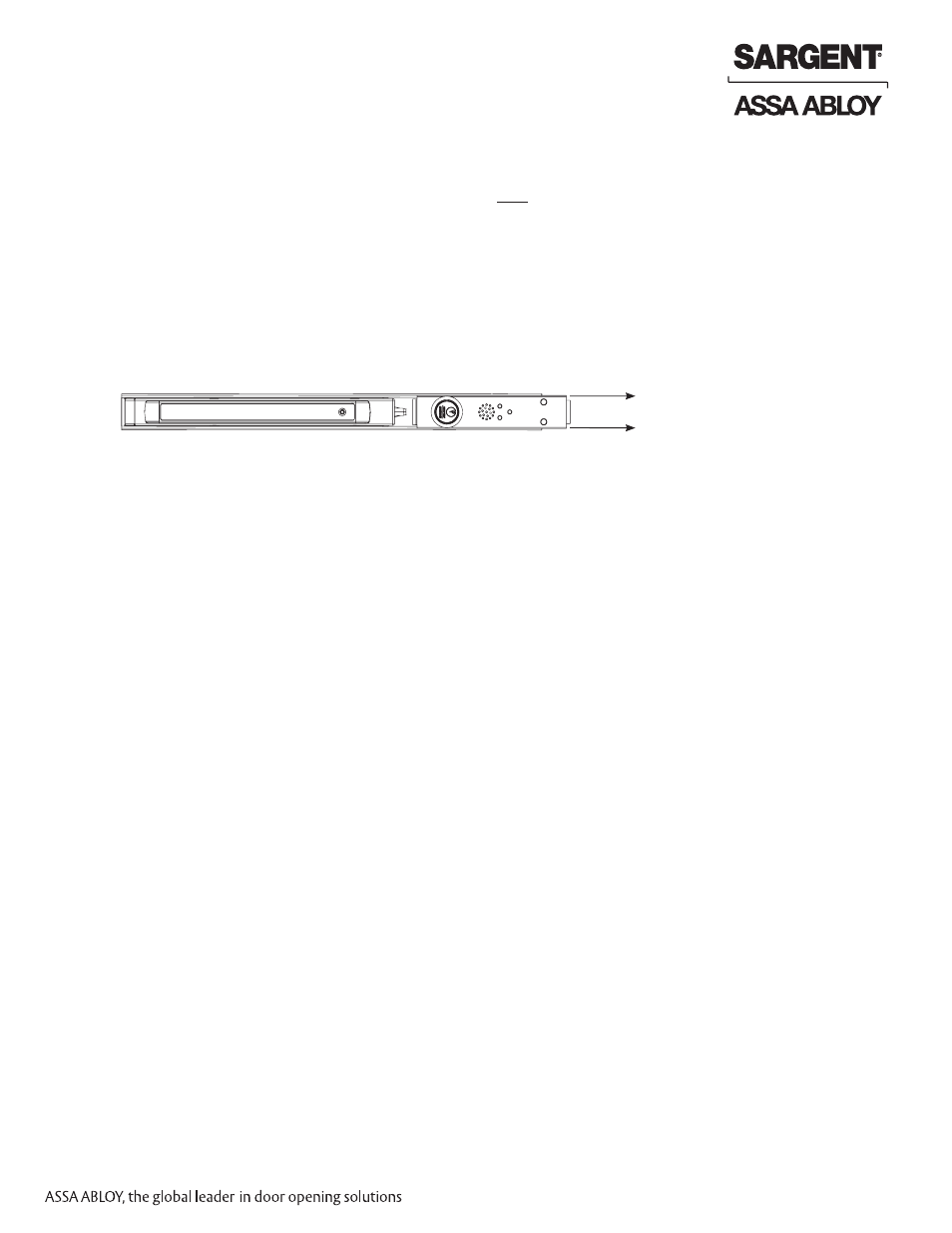
. Slowly slide insert assembly (2 inches) away from push bar (Fig. 6), carefully checking for any
additional wires required for TL- prefix.
D. Disconnect all wiring connectors before attempting to fully remove Beacon insert assembly.
E. Remove insert assembly by sliding out from rail assembly.
F. If replacing cylinder, go to
Section II.3 - Cylinder Installation/Replacement.
NOTE: For TL-BT-, retain existing Beacon harness for reuse.
G. Slide new Beacon insert assembly into rail assembly.
H. Complete wiring connections - refer to this manual’s example wiring diagrams in
Section III for
proper connections.
I. Reinstall mounting bracket and end cap.
Fig. 6
2. Kit Installation - Replacement/Servicing (Continued)