SARGENT NB-MD8600 Concealed Vertical Rod Exit Device for Metal Doors User Manual
Page 2
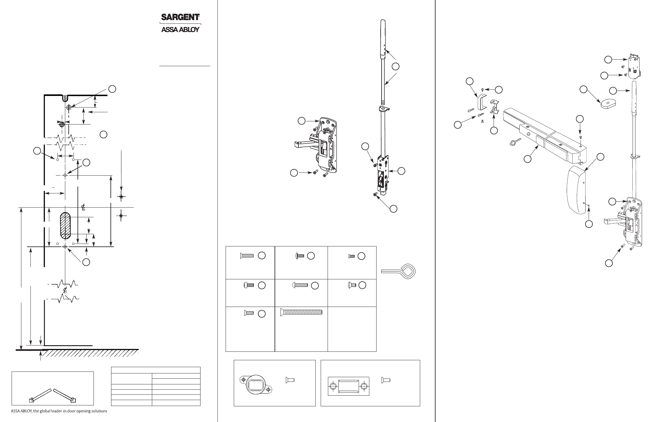
10) Slide rail assembly (J) onto center case
chassis (D).
11) Align holes for screws (BB).
12) Level rail.
13) Locate & mark holes for mounting plate (I)
on hinge side. Drill & tap (2) holes (4A).
14) Attach mounting plate (I) and secure rail
assembly (J) to door with (2) screws (EE).
15) Tighten screws (AA) to secure center case
chassis (D) to door.
16) Before closing door, check the following:
a) Push rail in to retract bolt.
b) Bolt stays retracted (Hold Back).
c) Bolt releases when door closes. Button
inside top of door hits frame.
d) Bolt engagement with strike 1/4"- 5/16".
e) Adjust bolts per step 7.
17) For NB-AD-8600: Attach 640 strike using
instruction sheet A8037 supplied with strike pack.
18) For NB-MD-8600 and 12-NB-MD-8600: Attach
650 top strike to frame with two #10-24 x 1/2" flat
head screws. See chart on left.
19) Attach cover (K) to center case chassis (D) with
(4) screws (CC).
20) Attach end cap (H) to mounting plate (I)
with (2) screws (CC).
21) Secure rail assembly (J) to chassis (D)
with (2) screws (BB).
Instructions for Installing
NB-AD-8600, NB-MD-8600 & 12-NB-MD-8600
Concealed Vertical Rod Exit Devices
without Bottom Bolt
2) Screw top bolt & rod assembly (A) into inner chassis (B).
3) Slide complete assembly into top of door.
4) Attach inner chassis (B) to door with screw (GG) using
hole (5A).
5) Then secure with screw (FF) using hole (3A).
6) Position chassis (D) over fillister head screw and attach to
door with (4) screws (AA) using holes (2A). Do not tighten yet.
Use chassis (D) to retract top bolt & rod assy (A) to adjust bolt
projection.
Note: Rod must be retracted while adjusting bolt projection.
Use chassis (D) to retract top bolt & rod assy (A).
7) Adjusting the top bolt & rod assembly (A)
1) 1/8" gap or less between door top and frame. Rotate
bolt to make even with top of the door.
2) 1/8" gap or greater. Bolt to extend above door equal to gap
minus an 1/8".
8) Slide rod silencer (G) over top bolt (F) onto rod,
followed by top chassis (E). Secure top chassis (E)
to door with (2) screws (HH) using holes (1A).
9) Install door into the frame using hinges.
Top bolt &
rod assembly
Fillister head
screw
#10-24 x 3/8"
Flat head screw
#10-24 x 1/2"
Inner
chassis
Center case
chassis
Flat head
screw
#10-24 x 3/4"
Chassis mounting screw
metal door application
(#10-24 x 3/4" ph. fl.hd.
mach. screws, 4 pcs)
End cap mounting bracket
(#10-24 x 3/4" ph. rd.
hd. mach. screw 4 pcs)
Rail mounting screw
(#8-32 x 3/8" ph. truss
head machine screw.
by finish 2 pcs)
Cover & end cap mounting
screw (#8-32 x 5/16" with
#6 ph. ov. u'cut hd. machine
screw, by finish 6 pcs)
Aligning and inner chassis
screw (#10-24 x 3/8" ph.
fillister hd. machine screw,
1 pcs)
Inner chassis bottom screw
& top strike screws
(#10-24 x 1/2" ph. fl.hd.mach.
screws, 3 pcs)
ET mounting screw
(1/4"-20 x 2 3/8" ph. fl. hd.
mach. screw 2 pcs)
Top case mounting screw
(#10-24 x 3/8" ph. ov. hd.
machine screw 2 pcs)
For 1 3/4" door length
shown size varies by 1/4"
depending on width of
cladding or inside panel
Manual dogging key
(not used with 12-)
To operate: Depress push
rail, insert hex key (or cylinder
key when used) and turn
clockwise.
Not furnished with 12-MD8600
CC
BB
AA
EE
FF
GG
HH
A
FF
D
AA
B
GG
Top chassis
Oval head screw
#10-24 x 3/8"
Truss head screw
#8-32 x 3/8"
Top bolt
Silencer
Oval head screw
#8-32 x 5/16"
End cap
Round head
screw
#10-32 x 3/4"
Mounting
plate
Rail assembly
Cover
Center
case
chassis
Flat head
screw
#10-24 x 3/4"
H
E
HH
F
G
BB
K
D
AA
CC
EE
I
J
Verify the correct exit device is being installed on the correct door. Function, finish and size
should all be verified.
Note: Before removing door from hinges determine the gap between top of door and frame.
This information is needed for step #7. Remove door from the frame.
INSIDE
LEFT HAND
REVERSE
BEVEL
RIGHT HAND
REVERSE
BEVEL
THIS EXIT DEVICE IS HANDED
CHECK HAND OF DEVICE AGAINST APPLICATION
OUTSIDE
Information for Cutting Rails
Rail Sizes
Door Widths
Max
Min
E
32"
24"
F
36"
33"
J
42"
37"
G
48"
43"
Oval head screw
#8-32 x 5/16"
CC
Note: 12-NB-MD8600 Series Exit
Devices require installation of
thermal pin to meet requirements
for fire rating.
Copyright © 2008, 2009 Sargent Manufacturing Company, an ASSA ABLOY Group company.
All rights reserved. Reproduction in whole or in part without the express written permission
of Sargent Manufacturing Company is prohibited.
A7002F: 6-1-09
FINISHED FLOOR
HINGE STILE
1-1/4"
1/4"
5/8"
GAP
36-3/4"
UNLESS
OTHERWISE
SPECIFIED
3-11/16"
41"
STD.
HGT.
4-1/2"
7/32" DIA
1-17/32”
1-1/4"
1/4"
Door prep shown is
the same for all less
bottom rod 8600
Exit Devices, except
the 12-NB-MD-8600
requires the thermal
pin that is supplied.
Note: If 100 Series
Auxiliary Control is
being used, door
must be prepped for
Aux Control prior to
installing device on
to the door. Aux
Control can be
installed after exit
device is installed.
See appropriate
instructions.
4A
1A
3A
5A
DRILL AND CUTOUT
THIS SIDE OF DOOR
ONLY
7/32" DIA.
C'SINK FOR
#10 SCREW
INSIDE SURFACE OF LHRB DOOR SHOWN
(2) 7/32" DIA & C'SINK
POSITION OF MOUNTING SCREW
HOLES ARE IDENTICAL FOR
EITHER HAND
DRILL AND TAP HINGE STILE FOR
#10-24 SCREW. USE MOUNTING
PLATE TO LOCATE HOLES.
7/8"
1) Drill, tap & cʼsink the door per template, except
for the (2) #10-24 (4A) on the hinge side.
For additional information, contact SARGENT at 1-800-727-5477
STRIKE PACK FOR NB-MD-8600 & 12-NB-MD-8600
650 TOP STRIKE
STRIKE (1 REQUIRED)
#10 X 1/2"
PHILLIPS FLAT HEAD
MACHINE SCREW
(2 IN PACK FOR
TOP STRIKE)
STRIKE PACK FOR NB-AD-8600
STRIKE (1 REQUIRED)
#10 X 1/2"
PHILLIPS FLAT HEAD
MACHINE SCREW
(2 REQUIRED)
640 TOP STRIKE
2A
(4) #10-24
TAPPED
HOLES
6-11/16"
2-3/4"
BACKSET
7/8"
OF CHASSIS