Alarmed exit devices al-80 series, Cylinder installation, Cylinder orientation – SARGENT AL - Alarmed Exit User Manual
Page 4
2
800-810-WIRE (9473) • www.sargentlock.com • A7884A
Alarmed Exit Devices AL-80 Series
5
/1
5
/0
8
C
o
p
yr
ig
h
t
©
2
0
0
8
S
A
R
G
EN
T
M
a
n
u
fa
c
tu
ri
n
g
.A
ll
ri
g
h
ts
re
se
rv
e
d
.
R
e
p
ro
d
u
c
ti
o
n
in
w
h
o
le
o
r
in
p
a
rt
w
it
h
o
u
t
th
e
e
xp
re
ss
w
ri
tt
e
n
p
e
rm
is
si
o
n
o
f
S
A
R
G
EN
T
M
a
n
u
fa
c
tu
ri
n
g
is
p
ro
h
ib
it
e
d
.
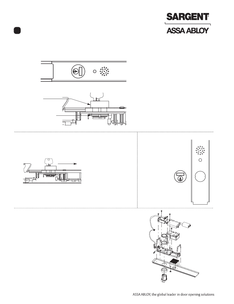
1. Prepare door according to template and Alarmed Exit instruction sheet.
2. Verify cylinder (size 41) is installed in rail insert with collar prior to installing exit device on door.
Installation and
Orientation of
Cylinder
To Add or Remove Cylinder
1. Remove Insert Assembly from rail by sliding toward rail end.
Cylinder Orientation
2.
Slide cylinder through collar into the insert as shown.
NOTE: Orientation of the cylinder.
Secure the cylinder with cylinder nut. Tighten firmly.
3.
Operate cylinder and verify cam is operating switch properly.
S
A
R
G
E
N
T
SARGENT
Cylinder Installation
3
Collar
Cylinder nut
Side View. Battery holder not shown.
Use caution not to damage wires
when installing cylinder nut.
- 8700 Surface Vertical Rod Exit Device NB-MD8600 Concealed Vertical Rod Exit Device for Metal Doors MD8600 Concealed Vertical Rod Exit Device for Metal Doors NB-MD8400 Series Narrow Style Concealed Vertical Rod MD8400 Series Narrow Style Concealed Vertical Rod 8900 Mortise Lock Exit Device 8300 8888 Reversible Rim Exit Device 8800 Rim Exit Device 8500 Narrow Design Rim Exit Device