SARGENT 5800 & 12-5800 Alarmed Exit Hardware User Manual
Optional mortise nuts with through-bolts
A7421B
A7421B
A
B
1. Assemble arm to closer with index mark on end of spindle 45° from axis of arm as illustrated below. Use washer and screw
to attach arm.
RIGHT HAND
ILLUSTRATED
C
Left hand door
Position of arm when
assembling to spindle
45
°
Closer spindle,
washer and screw.
Right hand door
45
°
Index mark
on spindle
Main
arm
Main
arm
Index mark
on spindle
Closer spindle,
washer and screw
.
With provided fasteners, secure closer body to door
with power adjustment away from hinge.
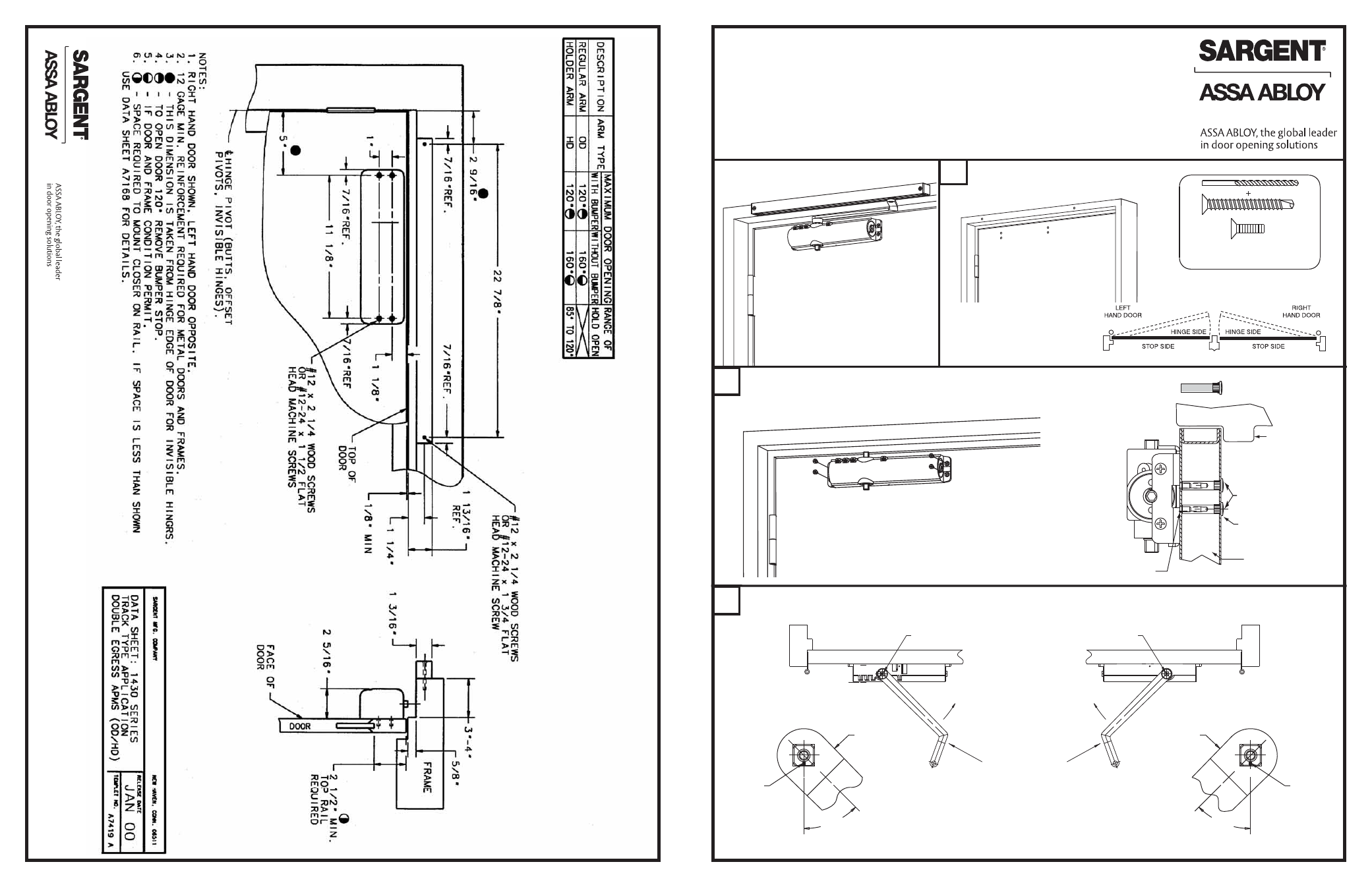
1431 (OD, ODB, HD, HDB ) DOUBLE EGRESS
PULL SIDE TRACK INSTALLATION INSTRUCTIONS
CAUTION: FAILURE TO INSTALL OR ADJUST PROPERLY
MAY RESULT IN INJURY OR DAMAGE
For assistance, contact SARGENT at 800-727-5477 or www.sargentlock.com
NOTE: AN AUXILIARY DOOR STOP IS REQUIRED
OR
Pre-drill - 3/32” holes for
self tapping screws or #16 drill for
#12-24 tap for machine screws
Drill and tap door and frame.
See page 4 for dimensions.
Optional mortise nuts
with through-bolts
Frame
Unreinforced door
Door stop
Mortise nut
Drill 3/8" dia.
Hole for mortise nut body.
Drill 1/4" dia. hole
for mounting screws
Copyright © 2006, 2008, Sargent Manufacturing Company, an ASSA ABLOY
Group company. All rights reserved. Reproduction in whole or in part without the
express written permission of Sargent Manufacturing Company is prohibited.
Copyright
©
2006, 2008, Sargen
t Manufacturing Company
, an A
SS
A
ABL
O
Y
Group company
. All right
s reser
ved. Reproduction in whole or in par
t without the
express writ
ten permission of Sargen
t Manufacturing Company is prohibited.