Adjust spring power according to chart, Adjustment instructions, Caution typical wiring – SARGENT 2900 Fire Guard Electromechanical Closer-Holder User Manual
Page 2
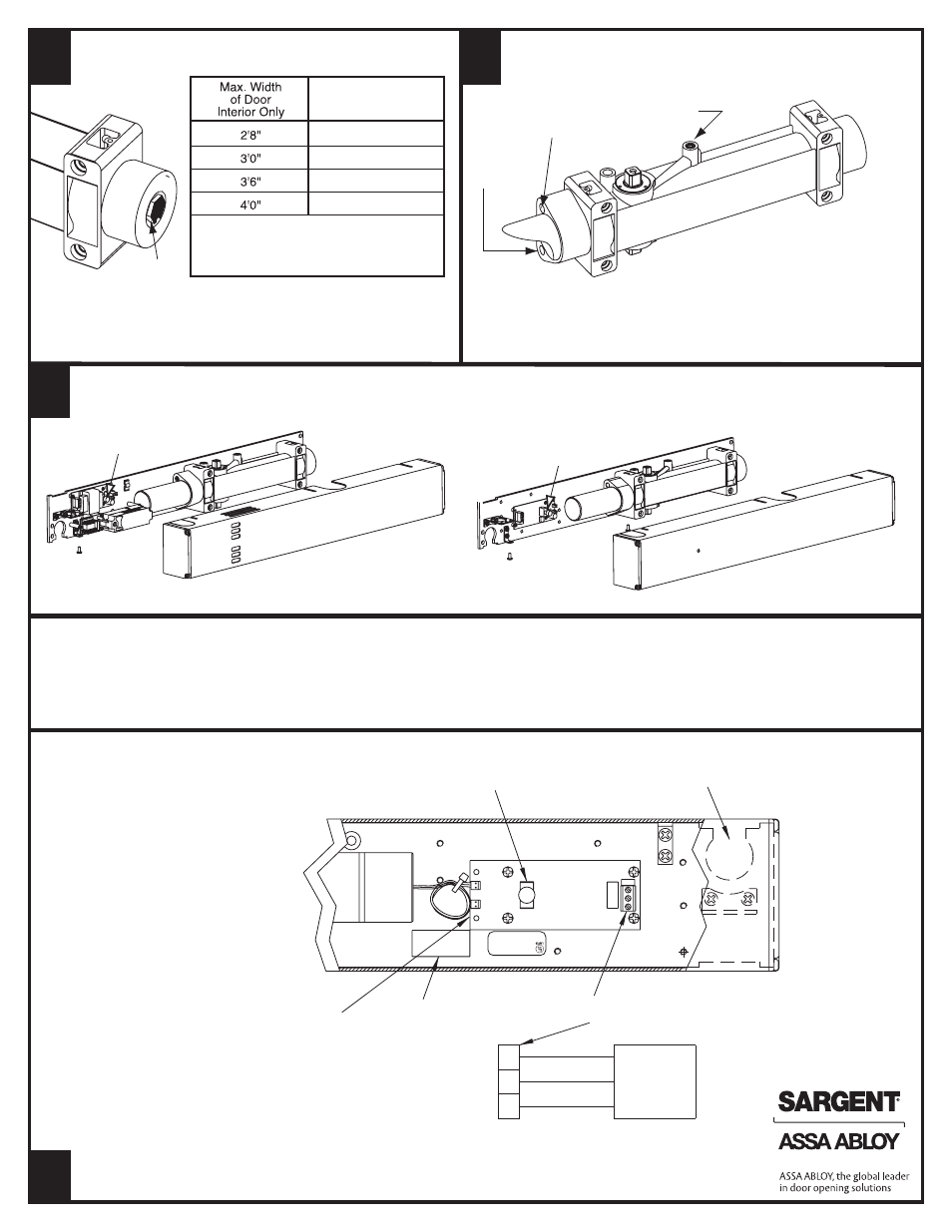
9-2980 Without Electronics
(not shown)
2980
Adjust Spring Power According to Chart
This valve
controls
Door Speed
This valve
controls
Latching
Speed
This valve
controls
Backcheck
Use 1/8" hex
socket wrench
to adjust valves
1. Assemble (3) short cover screws
(#8-32 x 5/16") into bottom of
closer body and cover mounting
bracket. Approx. one turn
CAUTION: Avoid
interference with
electronics and wires
during installation of cover
2. Install cover onto back plate
and closer assembly and
secure with screws
Turn the spring adjusting nut clockwise the required number of turns to match
door width as indicated in chart. Where strong drafts exist, increase spring power
as needed. 351 Series door closers leave the factory with the spring adjustment
set at eight (8) turns
First, adjust closers as directed
in steps D and E
Adjustment Instructions
To regulate closer: Turn valve screw clockwise to slow down,
or counterclockwise to speed up door movement
CAUTION: Set valve for a slight cushioning effect. It is damaging to the closer if the
checking action is too abrupt. Backcheck should never be used in lieu of a door stop
E
D
To Install Cover
F
The intensity of backcheck action is
regulated by valve shown. Turn clockwise
to increase – or counterclockwise to
decrease checking
Clockwise Turns
of Adjusting Nut
8
8
12
16
Maximum adjustment is
approximately 20 turns.
Do not forcibly extend
adjustment beyond limits.
12-2980
Test
Button
On/Off
Switch
5/8" Nut
CAUTION
Typical Wiring
1. DISCONNECT ALL POWER BEFORE BEGINNING INSTALLATION
TO PREVENT ELECTRICAL SHOCK AND EQUIPMENT DAMAGE
2. INSTALLER MUST BE A TRAINED, EXPERIENCED SERVICE
PERSON
Stand Alone Units 2980
• Wire stand-alone unit to appropriate
power supply and fire alarm
• Refer to data sticker for proper
input voltage and current specifications
• Energize power supply
• Open door to hold-open point.
Door should hold open
• Depress On/Off Switch. Door should
close and latch
• Adjustment of spring power may be
necessary to ensure proper latching
• Depress on/off switch again.
Open door to hold open postion.
Door will hold open
3. ALL WIRING MUST COMPLY WITH APPLICABLE LOCAL
ELECTRICAL CODES, ORDINANCES AND REGULATIONS
4. MAXIMUM WIRE SIZE IS 18AWG
For 9- companion units refer to
A7408 wiring Instructions
• Companion units are designed to work with
smoke detector units (12-2960, 12-2980, 12-2990,
12-2970) only.
• Wire companion unit to smoke detector unit
as shown on wiring diagram.
• Do not disconnect any existing wires on smoke
detector unit’s terminal strip.
• Energize power supply.
• Open doors to hold open point.
Doors should hold open.
• Depress On/Off button on smoke detector unit.
Doors should close and latch.
• Adjustment of spring power may be necessary
to ensure proper latching.
Opening for
Concealed Wiring
Earth Ground
Negative (-)
Positive (+)
3
2
1
Appropriate
Power Supply
Data
Sticker
Optional Remote
Release Connection
On/Off
Switch
Terminal Strip
for Power Input Connections
6
Companion Units
Smoke Detector Unit
Opening for
Concealed Wiring
Wire
Nut
7
9
UL
UL
Note: Caution input power supply must
match circuit board voltage rating,either
24VAC/VDC or 120 VAC
2
A7396D
Copyright © 2005, 2008, 2012, Sargent Manufacturing Company, an ASSA ABLOY Group company. All rights reserved.
Reproduction in whole or in part without the express written permission of Sargent Manufacturing Company is prohibited.