Lock body, Whit e ora nge green – SARGENT 10 Line Cylindrical Lock User Manual
Page 2
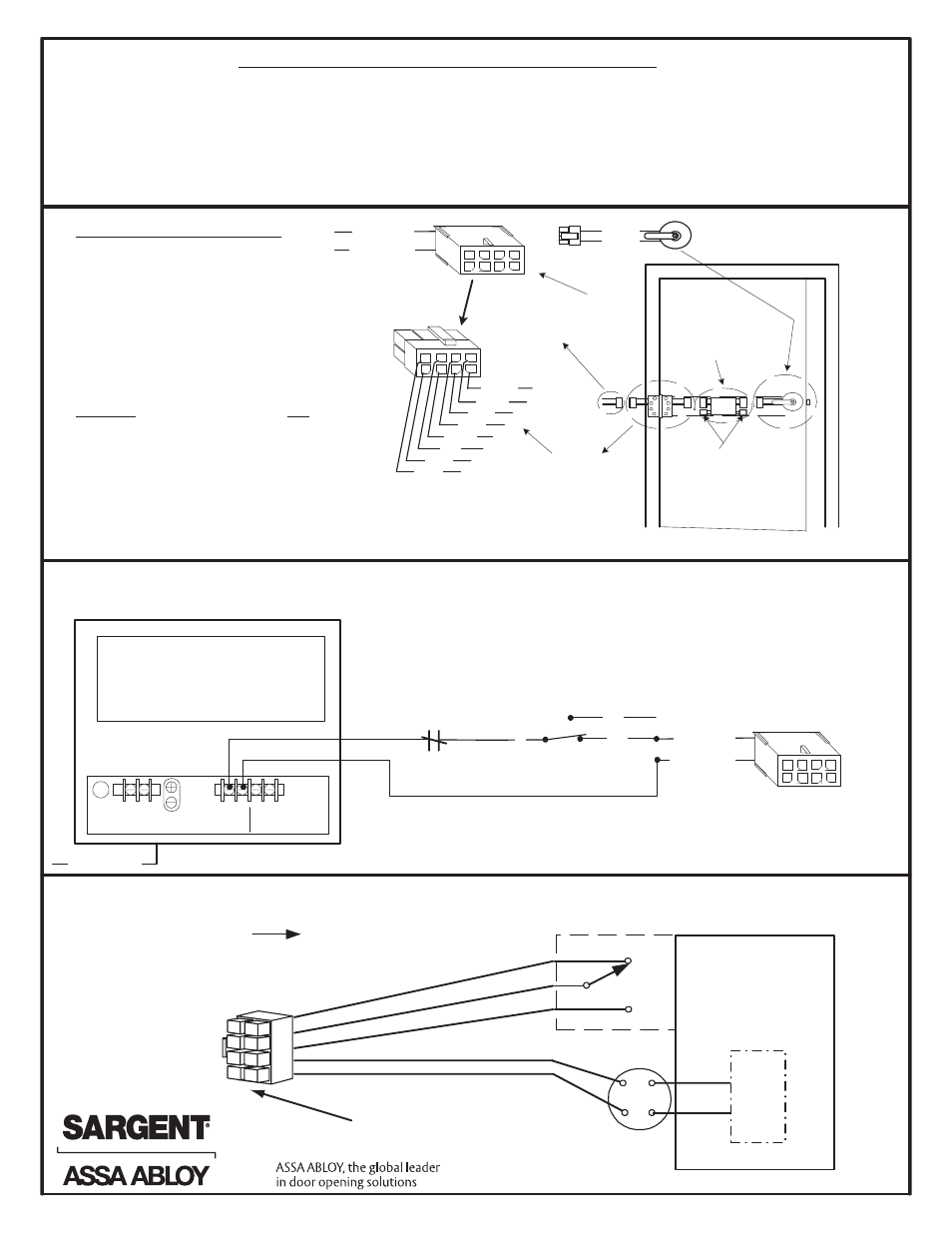
Sample wiring 10G70 Series Solenoid Locks with a 12VDC or 24VDC Regulated and Filtered Power Supply.
SARGENT offers both power supplies in 12VDC and 24VDC.
Wiring for RX-10G70/71 Series Solenoid locks. The lock is either 12VAC / VDC or a 24VAC / VDC lock body.
*
Note: Wire 10G70 (Fail Safe) Locks to switch as shown
For 10G71 (Fail Secure) Locks, wire the switch with a
normally open contact to the red wire of the Pigtail Harness
Installation Notes: 10G70, 10G71, RX-10G70, RX-10G71
• Lockbodies are available with either 12V or 24V solenoid
• Solenoids require either 12V or 24V AC transformer or a filtered and regulated power supply
• Lockbodies have an in-line bridge rectifier
• RX- Lockbodies are handed (RH, RHR, LH, LHR)
• Doors manufactured by ASSA ABLOY Group Companies are available pre-wired with ElectroLynx
• Doors without ElectroLynx will have to be hard wired
• 10 Line solenoids are not polarity sensitive
C
NO
Pigtail Harness
(2 wires with 8-pin connector)
L N
Input
120VAC
60HZ
+ - + -
Output 1 Output 2
12VDC OR 24VDC
Regulated and Filtered
Power Supply
120VAC L/N/G
GND
NC
Normally Closed Fire
Alarm Contact
(If Required)
1
7
5
6 4
3
2
8
Red
(+), 2
Black
(-), 1
Switch or
relay contacts
*
Plug into
8-pin hinge
connector
at door
8-wire
QC8 Electric Hinge
with 8-pin connectors
Installation and wiring instructions
Wire colors remain consistent with all
ASSA ABLOY products
1. While installing the lock into the door,
plug the lock's 8-Pin connector into
the door's wire harness
2. Wire the Pigtail Harness to transformer
or power supply
3. Verify correct voltage is being used
CAUTION: The AC/DC voltage must not exceed
13.2 VOLTS FOR 12V LOCKS AND 26.4V for 24V
locks. If voltage exceeds this value, the lock
solenoid may be damaged.
4. Plug Pigtail Harness 8-pin connector into
electric hinge 8-pin connector
5. Test lock: Applying voltage unlocks
fail secure lock and locks fail safe lock
Pigtail Harness
(QC2 Shown) 2 wire with
8-pin connector)
1
7
5
6 4
3
2
8
Black (-)
Red (+)
Green
Wh ite
Orange
Brown
Yellow
Blue
1
7
5
6 4
3
2
8
Red
(+), 2
Black
(-), 1
These plug into
each other
Note: Typical door harness location is
shown. Other locations may exist
depending on door type.
10G70 or 10G71 lock with
8-pin connector. Lock is
not polarity sensitive.
Red, 2
Black, 1
The 4 pin
connectors are
not used in
this application
Door harness
with 8 & 4 pin
connectors
LOCK BODY
+
-
SOLENOID
IN LINE BRIDGE
RECTIFIER
POWER 12VAC / VDC
or a 24VAC / VDC Lockbody
(+) PIN 2 RED
(-) PIN 1 BLACK
RX SWITCH
C
NC
NO
RX SWITCH- MONITORS
INSIDE HANDLE
(HANDED)
WHIT
E
ORA
NGE
GREEN
8
5
7
2
4
6
1
3
C PIN 3 WHITE
NO PIN 4 GREEN
NC PIN 5 ORANGE
© SARGENT Manufacturing Company All rights reserved
A6761C