Repair & replacement, C o r e, Motor, fan & fan guard – CCI Thermal Technologies FX5-SD - Explosion-Proof Electric Air Unit Heater User Manual
Page 15
15
repair & replacement
1. After repairing any component:
a. check that electrical connections are correct and secure
(see Figure 9),
b. remove any foreign material from enclosures,
c. install and secure all covers,
d. ensure that all fasteners are tight,
e. remove all foreign objects from heater, and
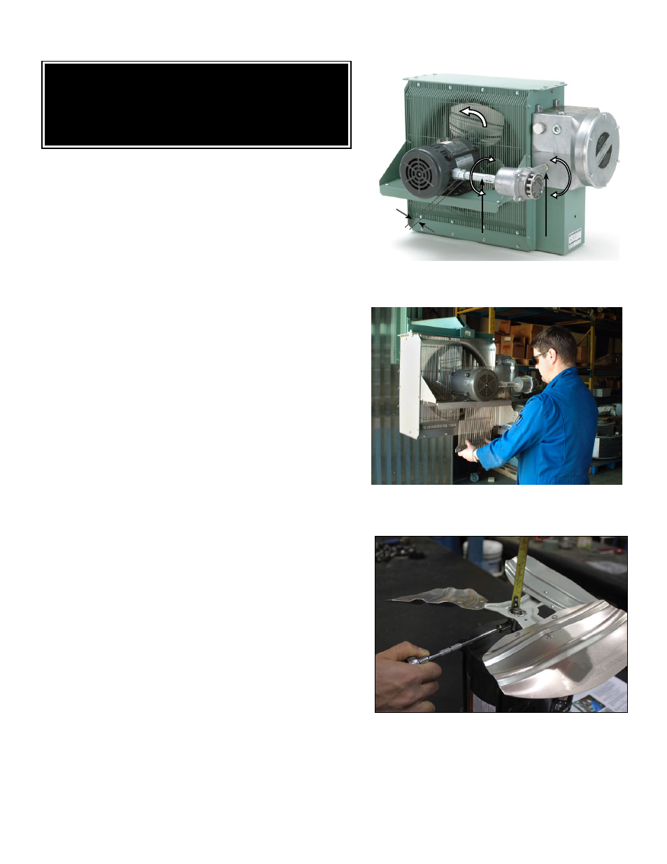
f. ensure air exits through louvers and fan rotates counterclockwise
when viewed from rear of heater (see Figure 10).
c o r e
The heater core is vacuum charged and not field repairable on Ruffneck
SD units. For questions of concerns regarding the replacement, please
contact CCI Thermal Technologies Inc..
motor, Fan & Fan guard
1. Remove bolts holding the motor to the motor mount. On units with
a builtin thermostat, remove the bolts on the back of the thermostat
enclosure.
2. Remove conduit #1 located between moto junction box and control
enclosure by turning it in the direction illustrated (see Figure 10). Note
conduits #1 and #2 are not interchangeable and have left hand threads on one
end, this end is indicated by a machined groove.
3. Remove the 2 piece fan guard assembly (see Figure 11).
4. Lift the motor assembly off the motor mount.
5. Before removing the fan, measure and record the location of the fan hub on the
motor shaft (see Figure 12). If difficult to remove, use a gear puller on the fan
hub.
6. To reassemble, place motor assembly onto motor mount and fasten the fan
guard to cabinet.
7. Simultaneously engage and tighten both ends of conduit #1 into enclosures.
Leave a 1/16” to 3/16” (1.6 to 4.8 mm) gap between the motor and fan guard
(see Figure 13). Adjust conduit #2 to center the fan in the shroud.
8. To ensure a minimum 5 thread engagement, threaded ends of conduits must
protrude a minimum of 1/16” (1.6mm) into enclosures. The groove on conduit #2
must not be more than 7/8” (22mm) from motor coupling (see Figure 10).
9. Bolt motor to motor mount. Manually spin the fan blade to ensure fan rotates
freely.
10. Air must exit through louvers and fan must rotate counterclockwise when viewed
from rear of heater (see Figure 10).
p r i n t e d c i r c u i t b o a r d
1. After removing the printed circuit board (P.C. Board) bracket assembly from the
control enclosure, separate the P.C. Board from the bracket by cutting off the
plastic spacers (see Figure 14).
2. Reinstall a new factory supplied P.C. Board onto the mounting bracket using new
non-conducting spacers of the same length. Spacers are supplied with a new
P.C. Board. Reinstall the control circuit ground wire to the printed circuit board
bracket (see Figure 9).
c o n ta c t o r
1. Loosen, but do not remove contactor mounting screws. Slide contactor off
mounting screws.
2. Replace with a factory supplied contactor of the same rating.
t r a n s F o r m e r
1. Replace with a factory supplied transformer of the same rating.
2. On the new transformer, select primary wires to match heater voltage. Ensure
that the correct transformer secondary lead is grounded (see Figure 9).
Individually terminate all unused wires using closed
end connectors.
FIGURE 10
Rotation
Air inlet
Conduit #2
Conduit #1
Remove
Install
7/8” (22mm)
(From groove to
face of coupling)
WARNING
Disconnect heater from power supply at integral disconnect or fuse box before
opening enclosures or servicing heater. Lock the switch in the “OFF” (open)
position and/or tag the switch to prevent unexpected power application.
IF INTEGRAL DISCONNECT IS BEING SERVICED, verify that power has
been disconnected at fuse box or main panel. Lock the switch in the “OFF”
(open) position and/or tag the switch to prevent unexpected power application.
Heater surfaces may be hot.
Remove
Install
FIGURE 11
FIGURE 12