CCI Thermal Technologies CA - Stuffing Box User Manual
Ca1001 stuffing box, Installation instructions
CA1001 STUFFING BOX
INSTALLATION INSTRUCTIONS
E-mail: [email protected]
www.ccithermal.com
MI167.Rev.7.01
Date of Issue: January 2013
Factory:
2721 Plymouth Drive, Oakville, Ontario, Canada L6H 5R5
Telephone: (905) 829-4422 Fax: (905) 829-4430
Toll Free: 1-800-410-3131
ISO 9001
Printed In Canada
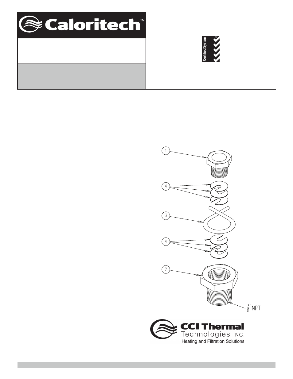
Fig.1
1.0
APPLICATION
1.1 The CA1001 is used around the capillary tube of an
AR or ARC control to hold the bulb into a well, or seal the
bulb into a tank.
1.2 AR thermostats with style 4 bulbs include a factory
installed non-removable stuffing box that may make the
use of a CA1001 unnecessary. AR thermostats style 9,
ARC limits and all thermostats and limits with optional
moisture resistant and explosion resistant enclosures
will require the CA1001 stuffing box if used as described
in 1.1.
1.3 It is always advisable to use a thermostat well where
high pressures, corrosive material or high or varying flows
are involved. Without a well, a leak or defect in the
thermostat would necessitate shutting down and drain-
ing the system. However, it should be noted that the use
of well may slow down the response time and increase
controller differential.
2.0
INSTRUCTION
2.1 The parts included with this kit are shown in Fig. 1.
2.2 Slide the small brass bushing over the bulb and onto
the capillary and position out of the way. The hex should
be towards the control and threads towards the bulb.
2.3 Slide the large brass bushing over the bulb positioned
with the hex facing the control.
2.4 Drop 3 split washers around the capillary and down
into the hollow of the large compression fitting.
It is very
important for a liquid light seal that the slots are
positioned alternately 180° from each other per Fig. 1.
2.5 Wrap the 5" graphite impregnated cord tightly around
the capillary and push it tightly into the compression fitting
hollow with a blunt tool being careful not to damage the
capillary.
2.6 Put at least one split washer in place and temporarily
thread the small bushing into place inside the large bush-
ing. This will help to compact the cord into a liquid tight
seal. Remove the small bushing, add the remaining 2
split washers again being sure to stagger the slots 180°
apart and reinstall the small bushing semi tight.
2.7 Position the assembly to the correct position on the
capillary, tighten the large bushing into its mounting
position in the tank or process, then tighten down the
small bushing to ensure a liquid tight seal.
2.8 If using the stuffing box assembly for mechanical
holding only in an air system or in a thermostat well the
extra care of assembly described in 2.4 thru 2.6 is not as
critical.
1.0 APPLICATION
1.1 The CA1001 is used around the capillary tube of an AR or
ARC control to hold the bulb into a well, or seal the bulb
into a tank.
1.2 AR thermostats with style 4 bulbs include a factory
installed non-removable stuffing box that may make the
use of a CA1001 unnecessary. AR thermostats style 9,
ARC limits and all thermostats and limits with optional
moisture resistant and explosion resistant enclosures will
require the CA1001 stuffing box if used as described in
1.1.
1.3 It is always advisable to use a thermostat well where high
pressures, corrosive material or high or varying flows are
involved. Without a well, a leak or defect in the thermostat
would necessitate shutting down and draining the system.
However, it should be noted that the use of well may
slow down the response time and increase controller
differential.
2.0 INSTRUCTION
2.1 The parts included with this kit are shown in Fig. 1.
2.2 Slide the small brass bushing over the bulb and onto the
capillary and position out of the way. The hex should be
towards the control and threads towards the bulb.
2.3 Slide the large brass bushing over the bulb positioned with
the hex facing the control.
2.4 Drop 3 split washers around the capillary and down
into the hollow of the large compressing fitting. It is very
important for a liquid light seal that the slots are positioned
alternately 180° from each other per Fig.1.
2.5 Wrap the 5” graphite impregnated cord tightly around the
capillary and push it tightly into the compression fitting
hollow with a blunt tool being careful not to damage the
capillary.
2.6 Put at least one split washer in place and temporarily
thread the small bushing into place inside the large
bushing. This will help to compact the cord into a liquid
tight seal. Remove the small bushing, add the remaining
2 split washers again being sure to stagger the slots 180°
apart and reinstall the small bushing semi tight.
2.7 Position the assembly to the correct position on the
capillary, tighten the large bushing into its mounting
position in the tank or process, then tighten down the
small bushing to ensure a liquid tight seal.
2.8 if using the stuffing box assembly for mechanical holding
only in an air system or in a thermostat well the extra care
of assembly described in 2.4 thru 2.6 is not as critical.