Parts diagram – CCI Thermal Technologies CF1 - ProVector Explosion-Proof Convection Heater User Manual
Page 7
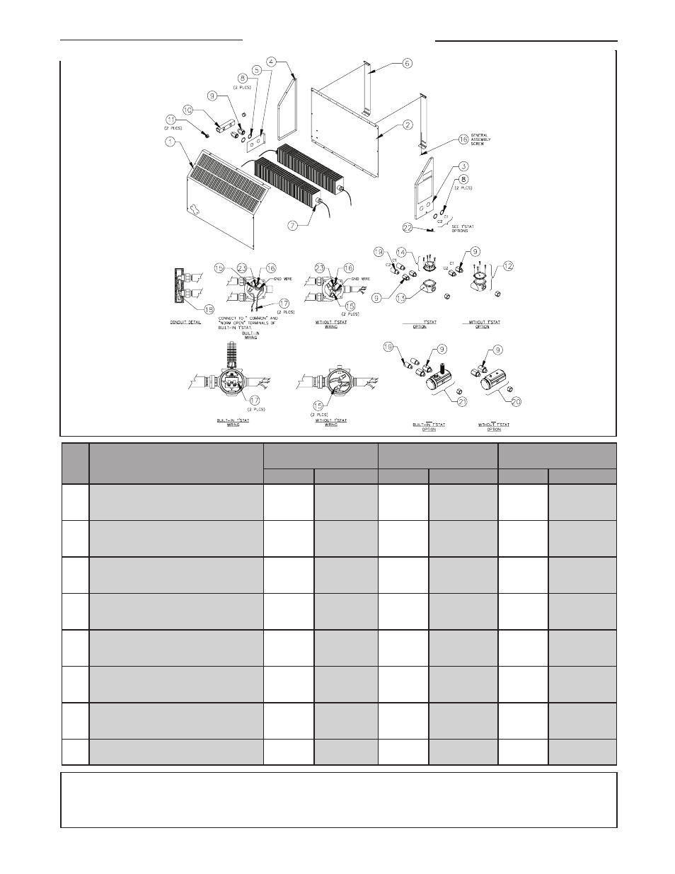
PARTS DIAGRAM
– 7 –
IIC
IIC
IIB BUILT IN
IIB
Item
#
Description
796 mm (31.3")
Cabinet Length
1256 mm (49.4")
Cabinet Length
1511 mm (59.5")
Cabinet Length
Part #
Qty
Part #
Qty
Part #
Qty
1
2
3
Panel, Front
Panel, Back
Panel, Right
6488
6487
6491
1
1
1
6493
6494
6491
1
1
1
6490
6489
6491
1
1
1
4
5
6
Panel, Left
Bracket, Finned Tube
Kit, Wall Mounting
6492
6485
6602
1
1
1
6492
6485
6602
1
1
1
9492
6485
6602
1
1
1
7
8
9
Finned Tube Assy c/w Element
Nut, 3/4" Aluminum Lock
Union, 3/4" NPT Male/Female CE IIC
*
6449
9627
2
4
4
*
6449
9627
2
4
4
*
6449
9627
2
4
4
10
11
12
Conduit, Element
Plug, 3/4" Ex-proof CE
Kit, Group B, (IIB) CE Enclosure
6497
7994
8024
1
2
1
6497
7994
8024
1
2
1
6497
7994
8024
1
2
1
13
14
15
Enclosure, Convector CE
Kit, Built-in XCT T'stat CE
Wire Connector, 150°C (302°F)
7992
8503
**
1
1
**
7992
8503
**
1
1
**
7992
8503
**
1
1
**
16
17
18
Screw, 10-24 x 1/2 in Thd Ct
Fork Connector, 12-10GA #10
Wire Connector, 300°C (+) 572°F (+)
4972
2088
6529
20
2
1
4972
2088
6529
21
2
1
4972
2088
6529
22
2
1
19
20
21
Tube, Convector Extension
Kit, Group A, B, C & D (IIC) x-Max® Encl.
Kit, Built-in XT T'stat
7202
9251
9252
2
1
1
7202
9251
9252
2
1
1
7202
9251
9252
2
1
1
22
23
Ground Lug CE
Ground Lug 14-6 gauge wire
7995
2793
1
1
7995
2793
1
1
7995
2793
1
1
NOTE:
* Contact factory for replacement finned tube kit.
** Customer supplied. Quantity varies: 1 for built-in t’stat option; 2 for remote t’stat option.
Dimensions of flameproof joints are other than the relevant minimum or maximum specified in Table 2 of IEC 60079-1:2007. Contact Manufacturer for
information regarding the dimensions of the flameproof joints.