Repair and replacement, Specifications, Warning – CCI Thermal Technologies CF1 - ProVector Explosion-Proof Convection Heater User Manual
Page 6
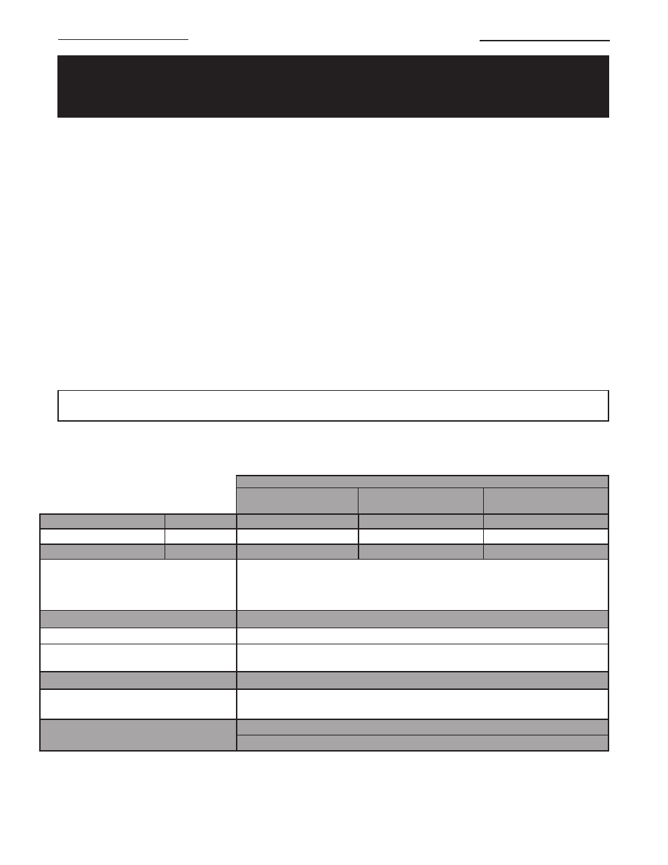
Cabinet Length
mm (in)
796 (31.3)
1256 (49.4)
1511 (59.5)
Net Weight
kg (lbs)
27 (58)
39 (86)
43.6 (96)
Shipping Weight
kg (lbs)
30 (65)
44 (95)
47.6 (105)
Enclosures
Defender® housing is cast aluminum with bolt on cover. Groups IIB only.
x-Max® housing is extruded aluminum with two screwed on covers. Groups IIC
only. For dry indoor use only. Do not immerse in water. Do not store or use in
areas exposed to rain or snow.
Mounting Brackets
Two 14 Ga. 0.075 in (1.90 mm) galvanized steel.
Heating Elements
Two Incoloy® sheathed elements.
Cabinet Material
14 Ga. steel. Rear panel is galvanized. Front and side panels are baked green-
grey epoxy powder coated with five-stage pretreatment, including iron phosphate.
Temperature Code Rating
T2 - 300°C (572°F); T3 - 200°C (392°F); T4 - 135°C (275°F)
Hazardous Locations Without Built-in T'Stat*
With Built-in T'Stat*
Class I, Div. 1 & 2, Groups A, B, C, & D; Class I, Zones 1 & 2, Groups IIA, IIB & IIC
Class I, Div. 1 & 2, Groups A, B, C & D; Class I, Zones 1 & 2, Groups IIA, IIB & IIC
Temperature Limitations
Operational: -45°C to 40°C (-49°F to 104°F )
Storage: -45°C to 80°C (-49°F to 176°F)
REPAIR AND REPLACEMENT
WARNING
Disconnect the power supply before installation of the heater. Lock the switch in the “OFF” (open) position
and/or tag the switch to prevent unexpected power application. Heater surfaces may be hot.
Allow the heater to cool down for a period of 2 minutes after operating before removing any enclosure covers.
FINNED TUBE/ELEMENT ASSEMBLY
A complete finned tube assembly is available from the factory. Refer to Parts Diagram for item numbers.
1. Remove the front cabinet panel (Item #1).
2. Remove convector electrical enclosure’s cover and disconnect wires.
3. De-couple two unions (Item #9) connecting convector enclosure and finned tube extension (Item #7).
4. Remove 3/4” NPT plug (Item #11) from element conduit (Item #10) and then pull out wire connector
and disconnect the wires.
5. De-couple remaining two unions and remove element conduit.
6. Remove union halves and lock-nut (Item #8) from ends of each finned tube requiring replacement
and set aside for re-use on new factory supplied finned/element assemblies.
7. Remove bolts from lower tabs of wall mount brackets (Item #6), remove heater from wall mount
brackets, and loosen the bolts from the finned tube bracket (Item #5).
8. Remove the damaged finned tube/element assemblies and install replacements.
9. Re-assemble heater using the reverse order of the preceding instructions.
Important: All threaded connections must be wrench tight with minimum of 5 turns engagement.
CABINET PANELS AND BRACKETS
Replacement cabinet panels and brackets are available from the factory.
NOTE:
For purposes of safety and convenience, all repairs and maintenance must be done with factory authorized parts and materials.
– 6 –
*Hazardous location ratings are dependant on the junction box used.
Please consult a customer service representative or the unit data plate for actual location ratings.
SPECIFICATIONS
0.75 - 3.00 (220V) &
3.30 (T2) - 3.60 (T2)
3.00 - 4.40 & 4.80 (240V)
Nominal kW
4.80 (380V) - 7.60