Viking Pump TSM635.3: Q-QS Universal Mag Drive User Manual
Page 9
SECTION TSM
635.3
ISSUE
C
PAGE 9 OF 13
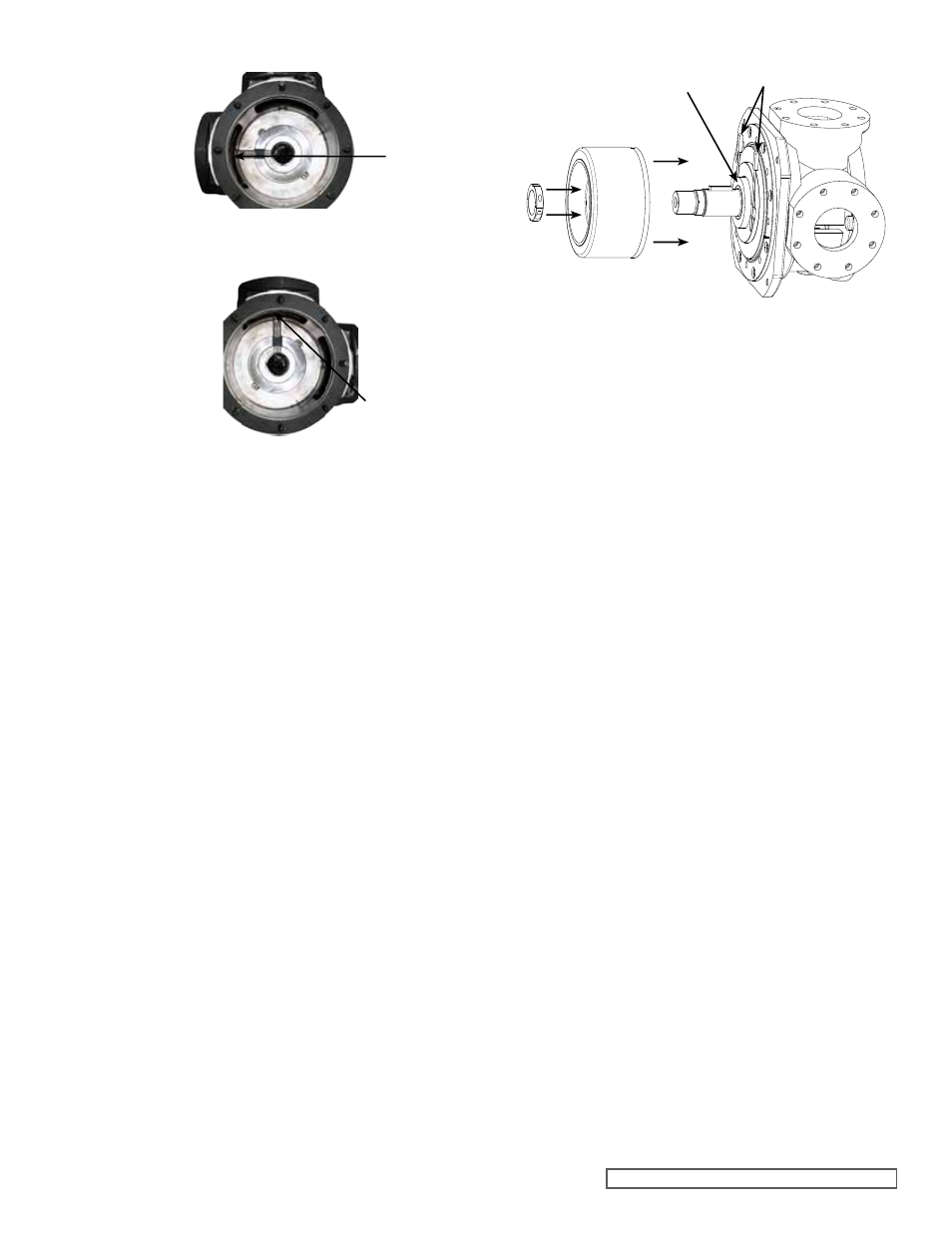
FIGURE 15
ADAPToR PLATE / CASING PoSITIoNING
(Q SIZE SHoWN)
ADAPToR
PLATE GRooVE
VIEWED FRoM
HEAD END
DISCHARGE PoRT
DISCHARGE PoRT
SUCTIoN
PoRT
SUCTIoN PoRT
ADAPToR
PLATE GRooVE
5. Having a second person on the opposite side of the
casing will help in placing the rotor and shaft into the
pump and prevent damage to the adaptor plate bushing.
Have the second person support the shaft through
the hollow shaft. Slide the shaft into the adaptor plate
bushing until the thrust washers come in contact. Make
sure that the thrust washers remain seated on the drive
pins and flat against the rotor or adaptor plate.
6. Apply a light oil to the second set of thrust washers on
the side of the thrust washer that will touch the inner
magnet or adaptor plate. Slide the thrust washer with
a groove over the shaft into the adaptor plate (bracket
side), groove facing out. Then install the key into the
shaft.
7. Clean the face on the inner magnet that faces the
adaptor plate. Place the second thrust washer that does
not have a groove onto the inner magnet so that the
blind holes in the thrust washer will line up with the drive
pins on the inner magnet. Support the inner magnet
using the inner magnet lift. Slide the inner magnet onto
the shaft until the thrust washers are almost touching.
Apply anti-seize compound to the threads of the split
locknut and install with the raised face towards the
inner magnet, do not tighten completely.
8. Place two feeler gauges (0.003”), one on each side of
the shaft, between the adaptor plate thrust washer and
the inner magnet thrust washer. Refer to
Figure 16.
This will establish the proper clearance for the thrust
washers. Tighten the locknut until the feeler gauges are
snug, but can still be removed. Do
NoT remove the
feeler gauges at this time.
9. Tighten the setscrew in the locknut. Check the feeler
gauges. If the gauges are too tight, loosen the setscrew
and locknut slightly and repeat tightening procedure.
Remove the feeler gauges. Check to make sure
the pump rotates freely by turning the inner magnet
assembly.
FIGURE 16
SETTING THRUST WASHER CLEARANCE
THRUST WASHER
FEELER
GAUGES
10. If the old shims are not reusable or if any parts have
been replaced, operating clearances will need to be
re-established. Refer to
“Adjusting End Clearance”
on page 10. Otherwise, place the head shims on the
head. There is an offset hole in the head, casing and
shims. These parts will only fit together one way. There
is a notch in the shims to indicate the offset hole. The
proper amount of shims should be used to provide the
correct end clearance (0.010” for sizes Q and QS).
Inspect the head o-ring; replace if needed. Refer to
Step 1 if PTFE (derivative) encapsulated. Lubricate the
O-ring and place on the head.
11. Ensure pipe plug is installed in the hole on the suction
side of the head, at the base of the idler pin. Ensure the
hole in the discharge side is unobstructed. See
Figure 17
on page 10.
12. Coat the ID of the idler bushing with a suitable lubricant
and place the idler on the idler pin in the head.
13. The head can now be assembled onto the pump. Tilt
the top of the pump head away from the pump slightly
until the crescent enters the inside diameter of the rotor
and rotate the idler until its teeth mesh with the rotor
teeth. Secure the head to the casing using eight nuts.
Check the end clearance. Refer to
“Adjusting End
Clearance” on page 10, if needed. Rotate the shaft by
hand to make sure it turns freely.
The pump head and casing should have been marked
before disassembly to insure proper reassembly. If not,
be sure the idler pin, which is offset in the pump head,
is placed between the port connections to allow for
proper flow of liquid through the pump.
14. Inspect the magnet to make sure it has not picked up
any foreign particles, which could damage the pump.
Inspect the canister bushing; replace if needed. See
“Installation of Bushings” on page 7. Lubricate the
ID of the canister bushing. Inspect the canister o-ring;
replace if needed. Refer to Step 1 if PTFE encapsulated.
Lubricate and place the o-ring into the groove in the
adaptor plate. Align the roll pin in the adaptor plate with
the corresponding hole in the canister and place the
canister onto the shaft. Secure the canister using eight
capscrews. Be careful placing the setscrews as this is
a strong magnet. Do not place fingers between magnet
and capscrews.
15. Secure the bracket to a base or other stable platform.
Inspect the canister to make sure it has not picked up