Pump disassembly, Warning – Viking Pump TSM635.3: Q-QS Universal Mag Drive User Manual
Page 5
54
59
65
66
57
46
47
45
44
43
40
63
35
38
39
37
36
60A
60
31
52
51
33
67
25
60A
60
13
62
6
4
1
2
5
3
14
7A
7
8
28
28A
12
27
6
5
58
SECTION TSM
635.3
ISSUE
C
PAGE 5 OF 13
ITEM
NAME oF PART
ITEM
NAME oF PART
ITEM
NAME oF PART
13
Capscrews for Adaptor Plate (8-Req’d)
40
Head and Idler Pin Assembly
57
Inner Magnet Assembly
25
Adaptor Plate Bushing
43
Studs for Head (8-Req’d)
59
Canister
31
Casing
44
Nuts for Head (8-Req’d)
60
Thrust Washer - Rotating (2-Req’d)
33
Adaptor Plate O-Ring
45
Relief Valve Gaskets (2-Req’d)
60A
Thrust Washer - Stationary (2-Req’d)
35
Head O-Ring
46
Capscrews for Relief Valve (8-Req’d)
62
Key for Rotor Shaft
36
Rotor and Shaft Assembly
47
Relief Valve
63
Shims for Head
37
Idler and Bushing Assembly
51
Studs for Flanges (16-Req’d)
65
Canister O-Ring
38
Idler Bushing
52
Nuts for Flanges (16-Req’d)
66
Split Locknut
39
Idler Pin
54
Capscrews for Canister (8-Req’d)
67
Adaptor Plate
ITEM
NAME oF PART
ITEM
NAME oF PART
ITEM
NAME oF PART
1
Locknut
6
Tapered Roller Bearing (2-Req’d)
14
Capscrews for Disassembly (3-Req’d)
2
Lockwasher
7
Bearing Housing
27
Bracket
3
End Cap
7A
Capscrews for Bearing Housing (6-Req’d)
28
Capscrews for Mounting Bracket (2-Req’d)
4
Outer Bearing Spacer
8
Inner Bearing Spacer
28A
Capscrews for Bracket (2-Req’d)
5
Lipseal (2-Req’d)
12
Grease Fitting
58
Outer Magnet Assembly
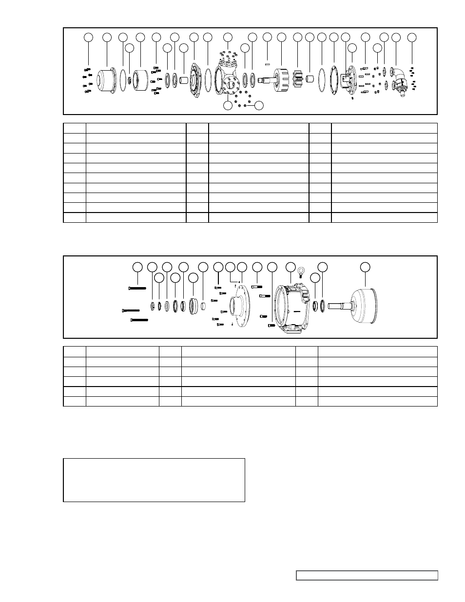
FIGURE 6
ExPLoDED VIEW – UNIVERSAL MAG DRIVE PUMP CANISTER THRoUGH RELIEF VALVE
FIGURE 7
ExPLoDED VIEW – UNIVERSAL MAG DRIVE PUMP BRACKET AND oUTER MAGNET ASSEMBLY
PUMP DISASSEMBLY
WARNING!
Refer to DANGER & CAUTIoN listed on page 2
before proceeding.
NoTE: Some steps require a second person for ease
of disassembly.
1. Drain the liquid being pumped by removing the two
drain plugs (if present). Both are located in the bottom
of the casing. Once the liquid has drained, replace the
plugs.
2. Refer to Figures 6 and 7 for the names of parts.
3. Use a non-magnetic surface to disassemble the pump.
4. Mark the head (40) and casing (31) before disassembly
to insure proper reassembly.
5. To inspect the head and pin assembly (39 and 40) and
idler and bushing assembly (37 and 38), remove the
head nuts (44).
6. Remove the head from the pump. Tilt the top of the
pump head back during removal to prevent the idler
from falling off the idler pin. If the casing was not
drained in Step 1, be careful of the liquid draining out
between the head and casing. Avoid damaging the
head shim set (63) since all shims are required to
maintain end clearance. Inspect the O-ring (35). Do
not remove the O-ring from the plate adaptor / casing