Pump assembly, Danger, Caution – Viking Pump TSM635.3: Q-QS Universal Mag Drive User Manual
Page 8
SECTION TSM
635.3
ISSUE
C
PAGE 8 OF 13
DANGER !
Follow these directions exactly to avoid injury
to self or damage to the pumping unit. Be
careful to keep the inner and outer magnets at
least (1) foot apart until step 17. Do not engage
the magnets in any other fashion.
CAUTIoN !
Do not place fingers onto the front of pump
mounting flange. Align the canister into bore
of the bracket and gently slide it in. When the
magnets start to engage, the unit will finish
engagement on its own very rapidly unless the
5/8” x 6” capscrew is properly used. Make sure
fingers are not on the front of the pump. See
Sequence in Figure 18.
DANGER!
Be certain that the driving means (motor, tur-
bine, engine, etc.) has been “locked out” or
made non-operational so that it cannot be
started while work is being done on pump.
PUMP ASSEMBLY
FIGURE 14
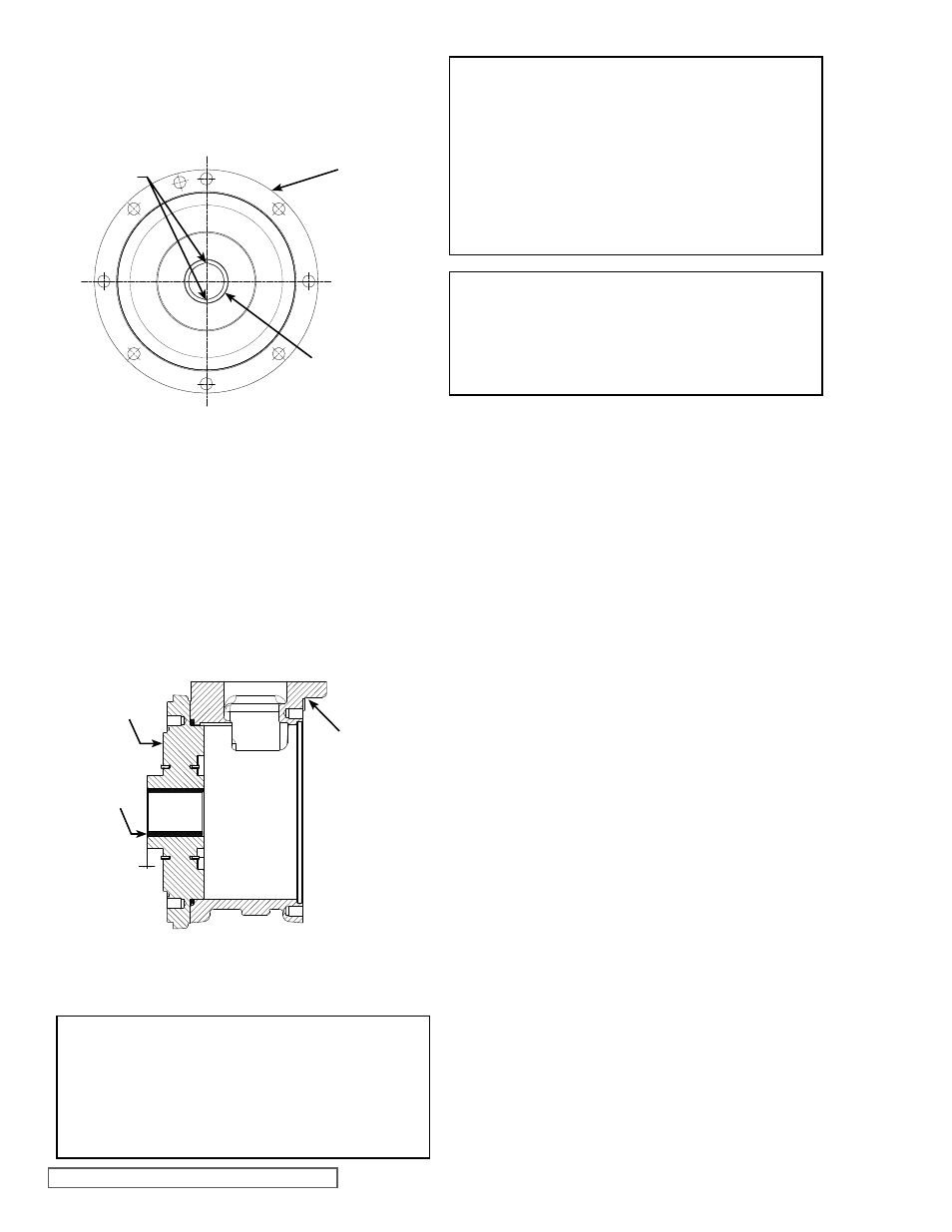
ADAPToR PLATE BUSHING PoSITIoN
ADAPToR
PLATE
BUSHING
CASING
INCH MM
.000 0.000
-.005 -0.127
NoTE: Some steps require a second person for ease
of assembly.
Use a suitable lubricant compatible with the fluid being
handled when reassembling the pump.
Inspect all parts, especially drilled holes in the casing (for
draining) to make sure they are not plugged. Replace any
worn parts, remove any burrs and clean all parts before
assembling the pump. Use a non-magnetic surface to
assemble the pump.
1. If the adaptor plate O-ring on the casing side needs to
be replaced, apply a lubricant to the O-ring and place it
onto the casing side of the adaptor plate. If the O-ring
is PTFE (derivative) encapsulated, follow these special
instructions.
Do not attempt to reuse this type of O-ring if it has been
removed. Immerse a new O-ring in boiling water for
a few minutes. Remove it from the water and stretch
out the O-ring. This ensures it will fit into the plate or
groove without forcing the O-ring over a sharp edge.
Run hot water over the O-ring until it shrinks down tight.
Hot water makes the PTFE pliable and allows the inner
elastomer to pull the PTFE back to the original size. Dry
it with compressed air.
2. Position the adaptor plate so the adaptor plate groove
aligns to groove in the casing bore at suction port, see
Figure 15. Carefully slide the adaptor plate into the
bracket side of the casing. Use care to prevent cutting
the O-ring with the edge of the adaptor plate or casing.
Secure into position by tightening the eight capscrews.
3. Apply lubricant to the ID of the adaptor plate bushing.
Clean the rotor and shaft so it is free of dirt, grit and
other debris. Remove burrs around the keyway and
shoulder of the shaft.
4. Apply a light oil to the first set of thrust washers on
the side of the thrust washer that will touch the rotor
or adaptor plate. Place the thrust washer that does not
have a groove onto the shaft so that the blind holes in
the thrust washer will line up with the drive pins on the
back of the rotor. Place the thrust washer with a groove
onto the adaptor plate so that the groove in the thrust
washer will line up with the grooves in the adaptor
plate, see
Figure 15.
LUBE
GRooVES
BUSHING
CANISTER
FIGURE 13
CANISTER:
Figure 13 shows the proper orientation of the canister
bushing after installation. Bushing should be flush with or
up to 0.010” below bushing hub face. Be certain canister is
properly supported.
BUSHINGS:
Installing bushings may require a special fixture to ensure
proper positioning. Improper location may result in a pump
with excessive slip, pre-mature wear or requiring a large
number of shims.
The additional precautions listed below must be followed for
installation:
1. An arbor press must be used for the installation.
2. Be certain the bushing is started straight.
3. Do not stop the pressing operation until the bushing is in
the proper position; starting and stopping will result in a
cracked bushing.
4. After installation, check the bushing for cracks.