Pump rotation, Adjusting end clearance – Viking Pump TSM635.3: Q-QS Universal Mag Drive User Manual
Page 10
SECTION TSM
635.3
ISSUE
C
PAGE 10 OF 13
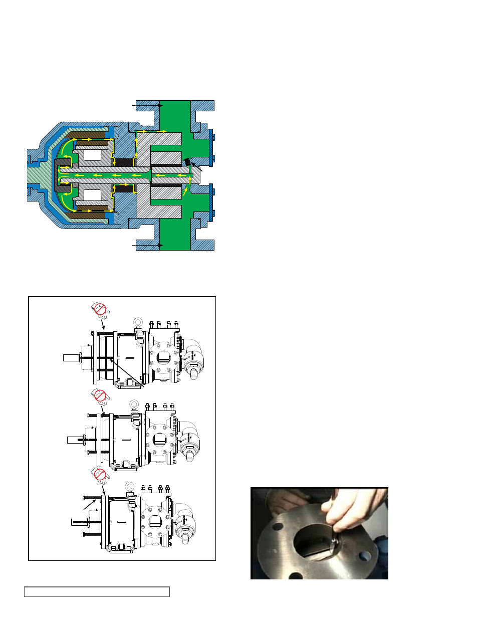
PUMP RoTATIoN
Process fluid is generally fed to the hollow shaft and idler
pin from the discharge side of the pump. Fluid is pushed into
the canister bushing and around the inside of the canister.
Then the fluid flows through the thrust washers and adaptor
plate bushing interface back to the suction side of the pump.
When the pump is operated in the opposite direction, the
fluid flow is reversed, see
Figure 17.
ADJUSTING END CLEARANCE
Standard end clearance of 0.010” is used on sizes Q and
QS. End Clearances are adequate for viscosities up to
2500 SSU / 540 cSt (SAE 40 lube oil at room temperature).
Higher viscosities require additional clearances. As a
general rule, the end clearance is doubled for higher
viscosities. For specific recommendations on end clearance
for high viscosity or for operating temperatures above
225°F (107°C), check with your Viking representative or
consult the factory. Use either of the following procedures
to properly adjust the end clearance when replacing
shims or reassembling the pump.
PROCEDURE A:
After the rotor has been installed and the locknut has been
positioned and retained, insert a feeler gage of the proper
end clearance into the port and between two rotor teeth, see
Figure 19. With the idler on the idler pin, place the head
into the pump casing. With the capscrews tight, the feeler
gage should fit snugly; otherwise shims should be added or
reduced in thickness until the proper clearance is attained.
FIGURE 19 PRoCEDURE A
FIGURE 18
PUMP ASSEMBLY SEQUENCE
Do NoT PLACE
FINGERS HERE
CAPSCREW
Do NoT PLACE
FINGERS HERE
ALL-THREAD RoD
Do NoT PLACE
FINGERS HERE
any foreign particles, which could damage the pump.
Place the canister sleeve onto the canister. Support the
pump with an overhead hoist and fixture while guiding
the canister into the bracket opening. Secure the pump
to the bracket using four socket head capscrews.
16. Inspect the bearing housing bearings and lipseals;
replace if needed. Refer to
“Disassembly / Assembly
of Bearing Housing”, page 7. Inspect the outer
magnet for any steel objects, which may be attached.
Remove any foreign material.
17. Insert three fully threaded 5/8” X 6” hex head capscrews
into the bearing housing until they are fully extended in
front of the bearing housing to control assembling the
pump, see
Figure 18. To keep the bearing housing and
bracket assemblies properly aligned and for additional
safety, it is recommended to use 2 lengths of all-thread
rod (12”) threaded into opposite capscrew locations in
the bracket and slide through the corresponding holes
in the bearing housing.
18. Back the capscrews off, being careful that the end of
the capscrew is positioned in the counterbore hole of
the bracket. Secure the bearing housing to the bracket
with six capscrews.
Make certain that the power supply to the pump is
“Locked-out”. Check that the pump rotates freely by
spinning the motor fan blades or pump shaft.
This figure is for illustrative purposes only.
Actual pump construction and location of ports varies.
SUCTIoN PoRT
DISCHARGE PoRT
PLUG
FIGURE 17
CIRCULATIoN oF LIQUID THRoUGH
UNIVERSAL MAG DRIVE PUMP