Viking Pump TSM635.3: Q-QS Universal Mag Drive User Manual
Page 6
SECTION TSM
635.3
ISSUE
C
PAGE 6 OF 13
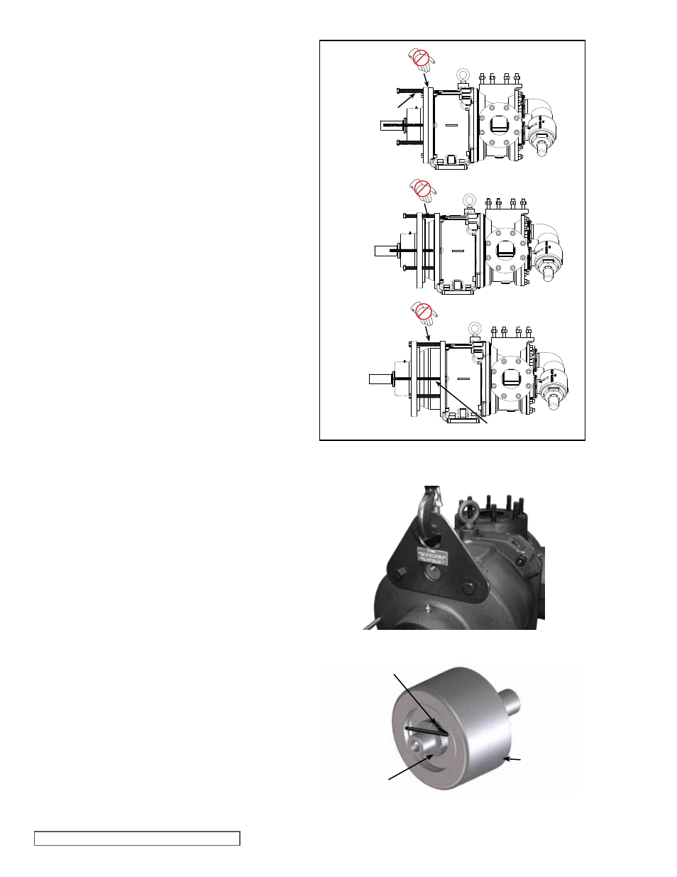
FIGURE 10
INNER MAGNET AND LoCKNUT ASSEMBLY
FIGURE 9
SETSCREW
LoCKNUT
INNER
MAGNET
ASSEMBLY
unless it is damaged, especially if it is PTFE (derivative)
encapsulated. If a new O-ring is required, See
“Pump
Assembly” on page 8.
7. Remove the idler and bushing assembly. Inspect the
idler bushing for wear. If the idler bushing needs to be
replaced, see
“Installation of Bushings” on page 7.
If further disassembly is required, proceed to the next
step.
8. If further disassembly is required, separate the pump
from the motor. Remove the six hex head capscrews
(7A) securing the bearing housing to the bracket.
Support the bearing housing with an overhead hoist
using a tool. See
Figure 9 dimensions for tool on page
3. Do not use tool to lift pump, use eyebolt on bracket.
9. Use the jackscrews (14) in the bearing housing to
separate the inner magnet (57) from the outer magnet
(58), see sequence in
Figure 8. To keep the bearing
housing and bracket assemblies properly aligned
and for additional safety, it is recommended to use 2
lengths of all-thread rod (12”) threaded into opposite
capscrew locations in the bracket and slide through the
corresponding holes in the bearing housing.
10. Slide the outer magnet assembly out of the bracket (27).
Visually inspect the outer magnets. Inspect the magnet
assembly for damage or wear; replace if needed. If
further disassembly of the bearing housing is required,
see
“Disassembly / Assembly of Bearing Housing”,
page 7.
11. Place the canister sleeve (3-810-025-999-00) into the
bracket over the canister (59). Remove the socket
head capscrews (28 & 28A) securing the bracket to the
pump. Support the pump with an overhead hoist and
fixture that is in-line with the center of gravity of the
pump. Slide the pump out of the bracket.
12. Remove the canister sleeve. Remove the socket head
capscrews (54) from the canister. If the canister was
not drained in Step 1, it will contain liquid. Use care
when removing the canister from the pump by pulling
it straight off. Inspect the canister bushing (64) for
wear. If the canister bushing needs to be replaced, see
“Installation of Bushings” on page 7.
13. Inspect the O-ring (65). Do not remove the O-ring from
the plate adaptor (67) / canister unless it is damaged,
especially if it is PTFE encapsulated. If a new O-ring is
required, See
“Pump Assembly” on page 8.
14. Insert a brass bar into the rotor (36) through a port
between two rotor teeth and remove the split locknut
(66), see
Figure 10. Support the inner magnet using
inner magnet lift (3-810-026-999-00).
Do not forget
this is a very strong magnet. Slide the inner magnet
assembly off of the shaft. Make sure the thrust washer
(60) does not fall off the inner magnet assembly. Place
inner magnet on non-magnetic cradle similar to
Figure
11. Inspect the magnet assembly for damage or wear;
replace if needed. If further disassembly is required,
proceed to the next step.
15. Remove the shaft key from the rotor shaft. Remove the
thrust washer (60A) from the adaptor plate if worn or
cracked. The rotor and shaft may now be removed by
tapping on the end of the shaft with a soft face hammer
(If a soft face hammer is not available, a regular
hammer may be used with a piece of hardwood). Take
FIGURE 8
PUMP SEPARATIoN SEQUENCE
Do NoT PLACE
FINGERS HERE
CAPSCREW
Do NoT PLACE
FINGERS HERE
Do NoT PLACE
FINGERS HERE
ALL-THREAD RoD