Elastomeric o-ring and ptfe wedge type, Danger – Viking Pump TSM630.3: N-RS Universal Seal User Manual
Page 9
SECTION TSM 630.3
ISSUE
H
PAGE 9 OF 13
FIGURE 10
For complete pump assembly instructions
see
Assembly, page 6.
1. Clean shaft and seal housing bore. Make sure they
are free of dirt, grit and scratches. Gently file a radius
on leading edge of shaft step over which seal is to be
placed.
NOTE: Never touch mechanical seal faces with anything
except clean hands or clean cloth. Minute particles can
scratch the seal faces and cause leakage.
2. Place tapered installation sleeve on the shaft (See
Figure 7, page 8).
3. Coat outside of tapered installation sleeve and inside of
rotary member of the seal with a generous quantity of
light oil. Grease is not recommended.
4. Start rotary member on shaft and ease over tapered
sleeve
(See Figure 10).
NOTE: Some PTFE wedge seals are equipped with
holding clips, which compress the seal springs. Remove
holding clips to release springs after seal is installed on
shaft.
ELASTOMERIC O-RING AND
PTFE WEDGE TYPE
5. Move rotary member so set screws are directly below
seal set screw access holes on side of bracket
(See
Figures 8 and 9). Tighten all set screws securely
to shaft.
NOTE: Be sure that the rotor and shaft are positioned
against the head before tightening set screws.
6. FOR “O-RING” GASKET TYPE MECHANICAL SEAL
SEAT (O-RING SEAL): Lubricate outer diameter of O-
ring seal gasket with oil. Flush sealing faces of both
rotary member and seal seat with oil and press seal seat
in to bore until back, unlapped face, is flush with bore.
Install seal holder and nuts and tighten securely.
FOR “CLAMPED-IN” TYPE MECHANICAL SEAL
SEAT (WEDGE SEAT): Flush sealing faces of both
rotary member and seal seat with oil and install seal
seat and seat gasket over end of shaft against machined
bracket face. Install other seal gasket, seal holder, seal
plate, capscrews and nuts and fasten securely.
7. Remove tapered installation sleeve.
DANGER !
Before starting pump, be sure all drive
equipment guards are in place.
Failure to properly mount guards may
result in serious injury or death.
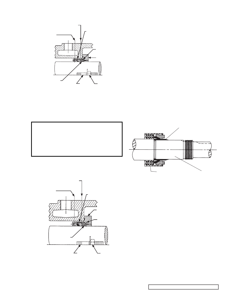
FIGURE 8
ELASTOMERIC O-RING SEAL
FIGURE 9
PTFE WEDGE SEAL
TAPERED INSTALLATION SLEEVE
SHAFT
MECHANICAL SEAL
ROTARY MEMBER
FLUSH CONNECTION
SETSCREW
ACCESS HOLE
SEAL SEAT
STUD
NUT
SEAL PLATE
SEAT GASKET
MECHANICAL SEAL
(ROTARY MEMBER)
SEAL HOLDER
SEAL GASKET
FLUSH CONNECTION
SETSCREW
ACCESS HOLE
SEAL SEAT
STUD
NUT
MECHANICAL SEAL
(ROTARY MEMBER)