Seal removal cartridge type, Elastomeric o-ring and ptfe wedge type, Seal installation – Viking Pump TSM630.3: N-RS Universal Seal User Manual
Page 8: Cartridge type
SECTION TSM 630.3
ISSUE
H
PAGE 8 OF 13
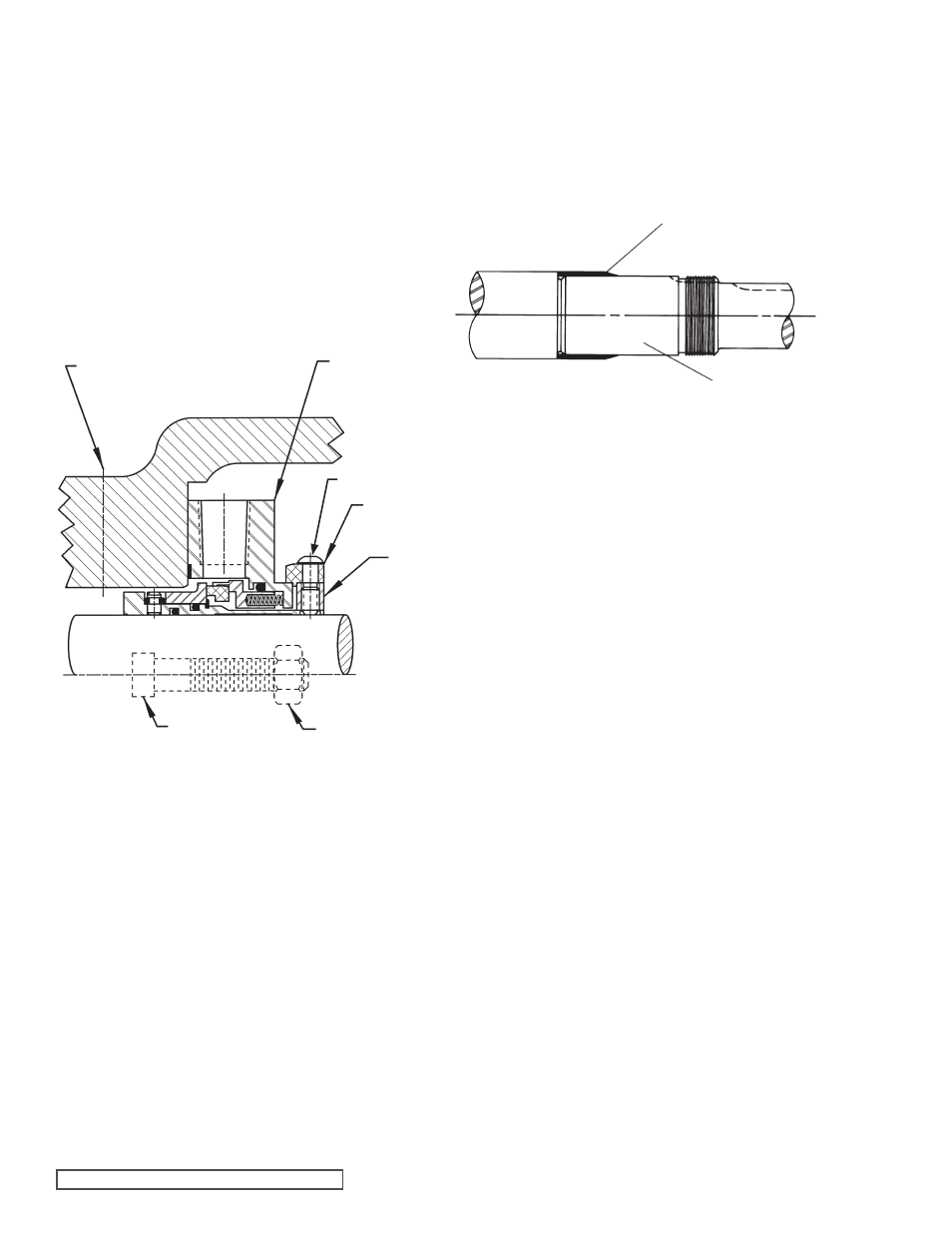
FIGURE 6
Cartridge Mechanical Seal
FIGURE 7
Elastomeric o-ring and PTFE wedge seals generally require
pump disassembly to be replaced
(See Disassembly, Steps
1-5,
pages 5-6).
1. Loosen nuts and remove seal holder, seal seat and seal
gasket(s).
2. Loosen setscrew in mechanical seal rotary member.
NOTE: Piping and/or plugs will need to be removed to
access setscrews.
If changing the mechanical seal is the extent of the
maintenance to be performed, then the rotor shaft
assembly only needs to be moved far enough to dislodge
the rotary member of the seal. To accomplish this, drive
the rotor/shaft assembly out until the rotor teeth extend
past the face of the casing
(4.5” for the N, or 3.5” for the
R and RS). Now push the rotor/shaft assembly back
into the casing. The rotary member of the seal should
SEAL REMOVAL
CARTRIDGE TYPE
Cartridge mechanical seals are designed so that they may
be replaced with minimal pump and piping disassembly. The
seal may be accessed by removing the bearing housing.
(See Disassembly, Steps 3-4, page 6).
1. Remove any circulation tubing connected to the seal
gland.
2. (see Figure 6 below) Loosen setscrews on the seal
collar to free the cartridge seal from the shaft.
3. Remove the two gland nuts and slide the cartridge seal
out through the bearing housing opening.
If the pump is to be disassembled further,
refer to
Disassembly, page 5.
ELASTOMERIC O-RING AND
PTFE WEDGE TYPE
1. NOTE: Burrs left on shaft can damage O-ring on seal
sleeve during installation. Inspect shaft for burrs and
remove any found with a fine grade of emery cloth.
2. Clean rotor shaft and face of seal chamber.
3. Place tapered installation sleeve on shaft. Coat rotor
shaft, tapered installation sleeve, and O-ring in the inside
diameter of cartridge seal sleeve with a generous amount
of light oil.
Refer to Figure 7.
4. Slide cartridge seal over installation sleeve on shaft until
it contacts the seal chamber face. Remove tapered
installation sleeve from shaft.
5. Follow steps 10-12 on page 6 under Assembly.
6. Install gland nuts studs and secure gland to bracket face.
NOTE: Turn shaft several turns while gland is loose to
center seal; then tighten gland tight enough to compress
gasket. Tighten only enough to contain leakage and not
to distort gland.
7. Lock cartridge seal drive collar to shaft and remove or
turn centering clips out of the way so as to clear the drive
collar.
8. Turn shaft by hand to check drive collar for runout.
9. Connect circulation line, or vent stuffing box seals without
circulation line until liquid is present on start up.
SEAL INSTALLATION
now be pushed far enough down the shaft for easy
removal. If the rotor/shaft assembly is to be completely
removed, then the remainder of the mechanical seal may
be removed in conjunction with Step 7 of
Disassembly,
page 6.
CARTRIDGE TYPE
TAPERED INSTALLATION SLEEVE
VENT CONNECTION
SHAFT
COAT ROTOR SHAFT, TAPERED INSTALLATION SLEEVE
AND INNER DIAMETER OF MECHANICAL SEAL WITH
LIGHT OIL BEFORE ASSEMBLY.
CARTRIDGE
MECHANICAL
SEAL
SEAL
COLLAR
CENTER
CLIPS
NUT
CAPSCREW
SETSCREW