Disassembly – Viking Pump TSM630.3: N-RS Universal Seal User Manual
Page 5
A
SECTION TSM 630.3
ISSUE
H
PAGE 5 OF 13
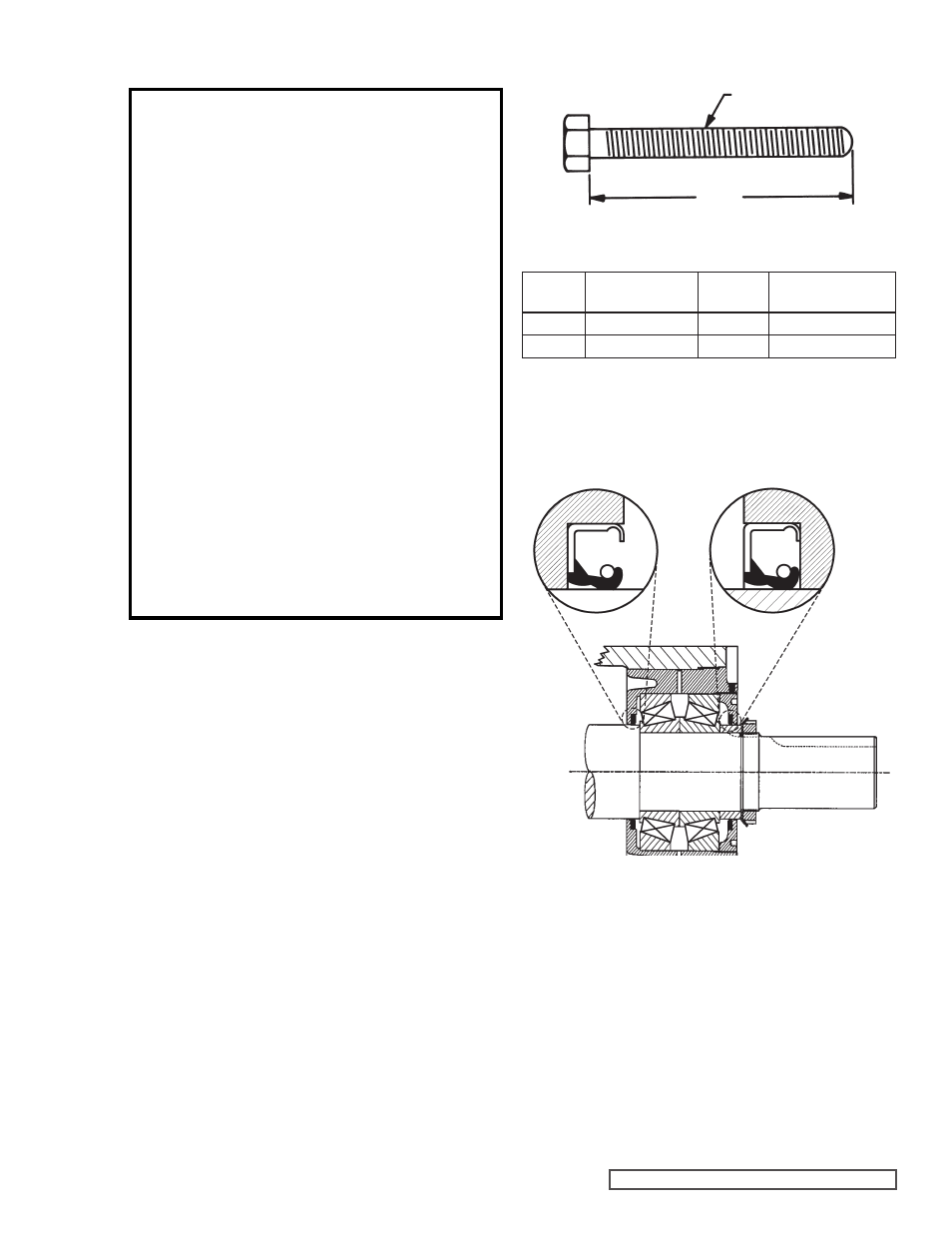
FIGURE 4
FIGURE 5
N-R BEARING HOUSING ASSEMBLY
DISASSEMBLY
DANGER !
Before opening any Viking pump liquid
chamber (pumping chamber, reservoir,
relief valve adjusting cap fitting, etc.)
Be sure:
1. That any pressure in the chamber has
been completely vented through the
suction or discharge lines or other
appropriate openings or connections.
2. That the driving means (motor,
turbine, engine, etc.) has been “locked
out” or made non-operational so that
it cannot be started while work is
being done on pump.
3. That you know what liquid the
pump has been handling and the
precautions necessary to safely
handle the liquid. Obtain a material
safety data sheet (MSDS) for the
liquid to be sure these precautions
are understood.
Failure to follow above listed
precautionary measures may result in
serious injury or death.
1. Mark head and casing before disassembly to insure proper
reassembly. The idler pin, which is offset in pump head,
must be positioned toward and equal distance between
port connections to allow for proper flow of liquid through
the pump.
Remove nuts from head. Jackscrews should be used to
back head away from casing. Proper size and length of
jackscrews for pump size are shown in
Figure 4. The
use of a hoist to support head will facilitate its removal.
Avoid damaging head gasket. Back head slightly away
from casing. Do not allow idler to fall from idler pin.
To prevent this, tilt top of head back when removing.
Remove head from pump. A lifting hook will provide
adequate connection for hoisting head. If a hoist is not
available, cribbing or blocking can be used to support
head. This will eliminate having to lift head into position
when reassembling pump.
If pump is furnished with pressure relief valve, it need
not be removed from head or disassembled at this point;
however, removing relief valve will lessen total weight of
part. Do not use chain or cable around relief valve body
to support head during removal.
Refer to Pressure
Relief Valve Instructions, page 11.
PUMP
SIZE
NO. SCREWS
USED
A
THREAD SIZE
(INCH)
N
2
4.00
0.50” - 13 NC
R & RS
2
4.50
0.63” - 11 NC
THREAD SIZE
MINIMUM LENGTH OF JACK SCREWS